
A drive (or amplifier) provides electrical power to a motor by regulating the motor speed and torque in response to commands from the motion controller. Some drives (amplifiers) have the capability to perform individual positioning moves, commonly termed point-to-point or indexing commands.
There are several key factors to consider when selecting an ac drive. For starters, consider the elements of the power supply available to the application.
These are the key criteria for the input power supply:
• Input voltage
• Number of phases (3 phase or 1 phase)
• Grounded or not grounded
• Input frequency (60 Hz or 50 Hz)
• Drive enclosure (NEMA 1, NEMA 12 ventilated, etc.)
• Motor cable length (also, shielded or unshielded)
• Motor cable type (fixed or flexing in machine operation)
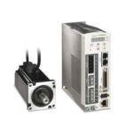
Next, look at the type of motor used in the application. What are the motor’s voltage, current rating, and horsepower? These can be found on the motor’s nameplate. This will help in determining the right drive for the application.
Important current parameters include:
• Base load current
• Peak current
• Peak current duty cycle description
In addition, some applications might require a dynamic braking module or a dynamic braking resistor. Also, determine what type of speed control is needed; i.e. servo, closed loop vector, open loop vector, volts/Hz.
Another consideration is the type of motor feedback. For closed-loop systems, the feedback can be any number of types including HTL/TTL, resolver, sin/cos 1 Vpp, multiturn absolute value EnDat, etc.
Next, look at the interface needs of the application. Almost all drive applications have an interface need for some combination of digital control, analog control and communications. These interface requirements are a key ingredient in the specification of operator and machine interaction to ultimately select a drive system that can meet or exceed the interface needs of the application. Key factors include:
• Number of digital inputs and outputs
• Number of analog inputs and outputs signals (and signal type including 0-10 VDC, 4-20 mA, or other)
• Communications (PROFIBUS-DP, PROFINET, EtherNet/IP, or other)
• Interface ports (RS232, RS485)
• PLC
• HMI
Consider any safety features that the drive may require. These can range from basic features such as brake control and stops to more advanced capabilities such as acceleration monitoring, speed monitoring and speed limits.
An often overlooked subject when specifying a drive system are the environmental conditions. Because electrical components such as drives must be cooled properly to ensure reliability, altitude and ambient temperature of the drive system have to be defined. Typical manufacturer’s data provide derating curves for drives that need to be applied when altitude or ambient temperature limits are exceeded.

Leave a Reply
You must be logged in to post a comment.