
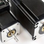
One of the most common motors used in motion control applications is the stepper motor. These motors are used mostly in positioning applications and have the advantage of being able to be very accurately controlled for the most precise positioning applications, down to fractions of a degree without the use of feedback devices such as encoders or resolvers. They are operated in open-loop (not closed-loop), without the need for tuning parameters as in closed-loop servo systems.
Steppers are generally classified by the number of allowable steps they can be commanded to move. For instance, a 1.8 degree step motor is capable of 200 steps/revolution (1.8 x 200 = 360 degrees, or one full revolution) in full-step mode. If operated in half-step mode, each step becomes 0.9 degrees and the motor can then turn 400 steps/revolution. Another mode called microstepping subdivides the degrees per step even further, allowing for extremely precise movements.
There are several different stepper motor technologies including permanent magnet motors, variable reluctance, and hybrid types. The principle of operation for stepper motors is fairly straightforward. Traditional variable reluctance stepper motors have a large number of electromagnets arranged around a central gear-shaped piece of iron. When any individual electromagnet is energized, the geared iron tooth closest to that electromagnet will align with it. This makes them slightly offset from the next electromagnet so when it is turned on and the other switched off, the gear moves slightly to realign. This continues with the energizing and de-energizing of individual electromagnets, thus creating the individual steps of motion.

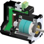
Hybrid stepper motors are more expensive than permanent magnet stepper motors but provide better performance with respect to step resolution, torque and speed. Hybrid steppers combine the best features of both the permanent magnet and variable reluctance type stepper motors. The rotor is multi-toothed like the variable reluctance motor and contains an axially magnetized concentric magnet around its shaft. The teeth on the rotor provide a path to help guide the magnetic flux to preferred locations in the airgap. This further increases the detent, holding and dynamic torque characteristics of the motor when compared with both the variable reluctance and permanent magnet motor.
Stepper motors are relatively inexpensive and can be run open loop, requiring no feedback devices. Also, because the speed is proportional to the frequency of the input pulses, a wide range of speeds is attainable. However, while stepper motors are capable of producing high torque at low speeds, they generally are well suited for lower power applications not for applications requiring lots of torque to move heavier loads. They are best for applications requiring the control of rotation angle, speed, and position.
A few drawbacks are that not properly controlling the motor can produce undesired resonance in the system. Also, stepper motors are generally not easy to operate at extremely high speeds. And as the motor speed increases, torque decreases.
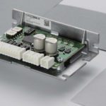
For two-phase stepper motors, there are two basic kinds of winding structures; unipolor and bipolar. A unipolar arrangement uses 6 wires but current can only flow in one direction. These types of motors also require a unipolar driver. A bipolar winding uses 4 wires and current can flow in 2 directions and it requires a bipolar drive. Bipolar motors are generally more efficient and can provide more torque than unipolar models, although they can heat up faster than unipolar motors.
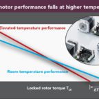
A stepper motor’s low-speed torque varies directly with current. How quickly the torque falls off at higher speeds depends on a number of factors such as the winding inductance and drive circuitry including the drive voltage. Steppers are generally sized according to torque curves, which are typically specified by the manufacturer.

Leave a Reply
You must be logged in to post a comment.