
Position measuring devices that rely on the principle of mutual induction include resolvers, linear variable differential transformers (LVDTs), and inductive encoders. Two of these technologies — resolvers and LVDTs — are based on the construction and operation of a transformer.
In the case of an LVDT, voltage is applied to a primary winding and induced in two secondary windings — located on either side of the primary — via a ferromagnetic core. Distance is determined by the differential voltage output by the two secondary windings, and direction is determined by whether the output voltage is in phase or out of phase with the primary voltage.
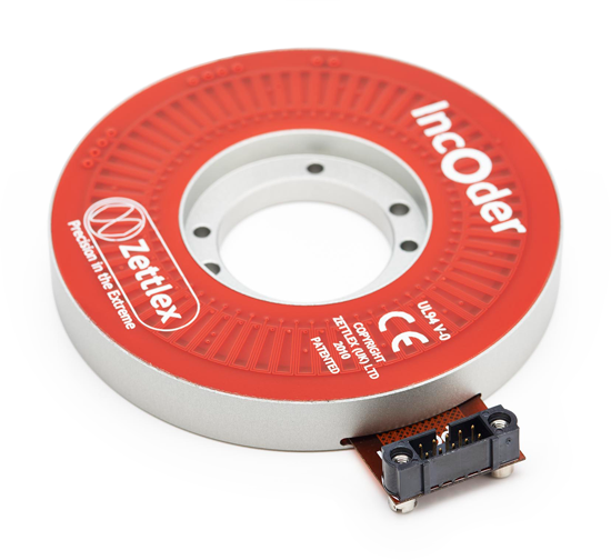
Image credit: Zettlex
In the case of a resolver, a rotary transformer applies voltage to the primary winding, which is located on the rotor. Voltage is then induced in two secondary windings, oriented at 90 degrees as sine and cosine, on the stator. Position is determined by the ratio of the voltages in the secondary windings, and direction is determined by analyzing which secondary voltage (sine or cosine) is leading.
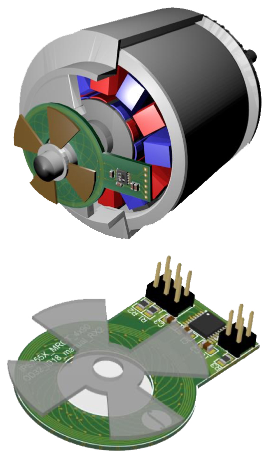
Image credit: Renesas
Inductive encoders are similar to LVDTs and resolvers, but instead of using traditional windings, they use flat coils (sometimes referred to as “traces”) manufactured onto printed circuit boards. Rotary inductive encoders contain two main parts — a stator (also referred to as the sensor) and a rotor (also referred to as the target).
The stator contains a transmitter coil and two (or sometimes more) receiver coils, printed onto the circuit board – or in some cases, directly onto the stator substrate. The receiver coils are printed so that they produce sine and cosine waves. In many designs, electronic circuitry for signal processing is also integrated onto the stator. The rotor, or target, is passive and is either made of ferromagnetic material or made of a substrate containing layers, or patterns, of conductive material such as copper.
When voltage is applied to the transmitter coil on the stator, or sensor, an electromagnetic field is produced. As the rotor, or target, passes over the sensor, eddy currents are generated on the surface of the target. These eddy currents generate an opposing field, which reduces the flux density between the sensor and the target, causing a voltage to be generated at the receiver coils on the sensor. The amplitudes and phases of the receiver voltages change as the target moves, and the position of the target can be determined from these voltages.
Inductive encoders are also available in linear versions. Here, the target is a linear scale with ferromagnetic (or electrically conducting) gratings, or stripes. The sensor (also referred to as the read head) contains the transmitter and receiver coils as well as electronics for signal processing. As the read head travels along the scale, the gratings of the scale cause variations in the voltages induced in the receiver coils, and these voltages indicate the sensor’s linear position.
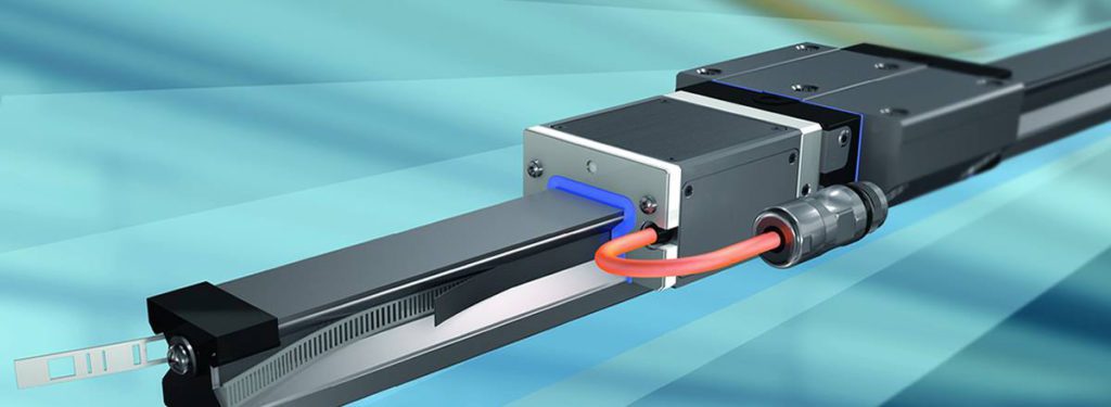
Image credit: Bosch Rexroth
Inductive encoders provide absolute position information and have accuracies that fall between that of magnetic and optical technologies — without the strict mounting considerations of optical encoders. And they’re insensitive to nearly all forms of contamination or interference, including liquids, dirt and dust, magnetic fields, EMI, and even severe vibrations. For rotary measuring applications, the printed circuit board construction of inductive encoders gives them a much smaller form factor and more design flexibility than their resolver counterparts.


Leave a Reply
You must be logged in to post a comment.