
A linear variable differential transformer (LVDT) is an absolute measuring device that converts linear displacement into an electrical signal through the principle of mutual induction. Its design and operation are relatively simple, providing extremely high resolution in a device suitable for a wide range of applications and environments.
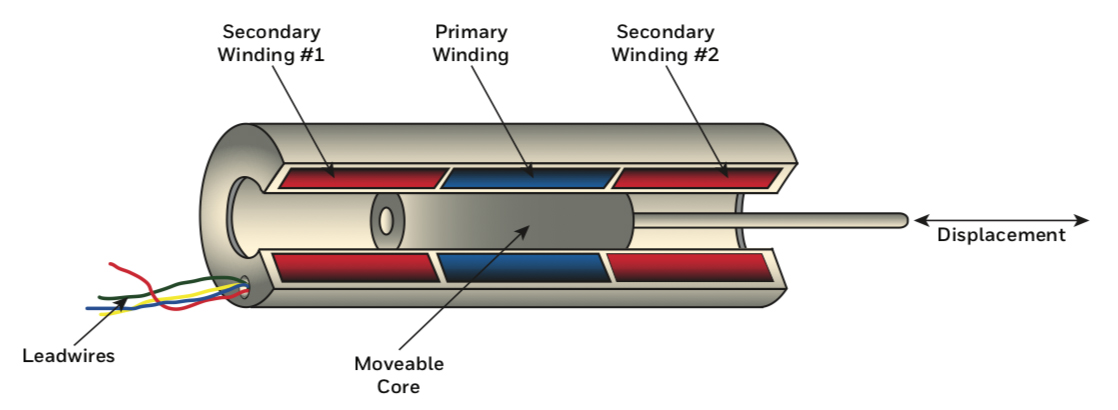
The main components of an LVDT are a transformer and a core. The transformer consists of three coils — a primary and two secondaries (S1 and S2) — wound on a hollow form, which is typically made of glass-reinforced polymer. The coils are arranged such that the primary coil is located between the two secondary coils, which are symmetrical and wound in series but in opposite directions (referred to as series-opposed winding).
The core is made of magnetically permeable material and moves freely inside the bore of the transformer. A non-ferromagnetic shaft, or push rod, is coupled to the core and connects to the object being measured.
When voltage is applied to the primary winding, the resulting flux is coupled to the secondary windings by the core. This induces voltages (often denoted E1 and E2) in each of the secondary windings. The differential voltage in the secondary windings determines the distance moved, and the phase of the voltage indicates the direction of movement.
Here’s how it works…
The series-opposed winding of the secondary coils means that when the core is at the center of the transformer (equidistant between the two secondary coils), the induced voltages have equal amplitude but are out of phase by 180 degrees. Thus, the induced voltages cancel each other, and the output voltage is zero. (This is often referred to as the null point.)
When the core moves to one side — toward S1 for example — the secondary coil on that side becomes more strongly coupled to the core, causing the induced voltage (E1) of that secondary to be higher than the induced voltage (E2) of the opposite secondary (S2). The differential voltage output (E1 – E2) determines the amount of movement.
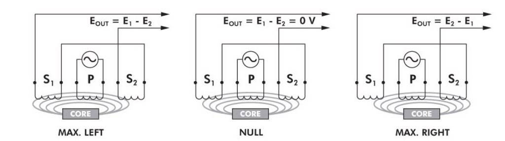
Image credit: TE Connectivity
The induced voltage (E1) of the first secondary coil is in-phase with the primary voltage, indicating the direction of movement. Conversely, when the core moves to the other side of the transformer, the induced voltage (E2) of that secondary coil is out of phase with the primary voltage, indicating movement in the opposite direction.
The output of an LVDT is a direct and linear function of the input across its specified measuring range, although linearity falls off as the core reaches or exceeds the ends of its range. However, it is possible to use an LVDT beyond its specified range, in some cases, with a pre-defined table or polynomial function to compensate for the nonlinearity.
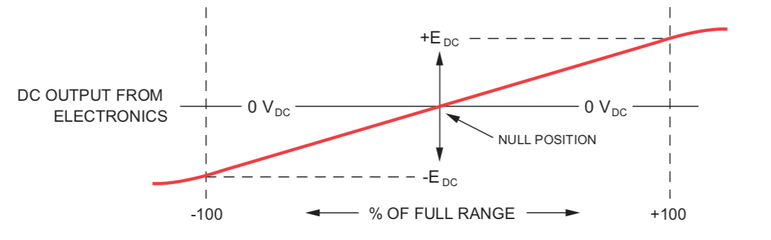
Image credit: TE Connectivity
An LVDT contains no electronics, but external electronics — referred to as a signal conditioner — include an oscillator to generate the drive signal, along with a demodulator, an amplifier, and a low-pass filter to convert the AC output voltage to a DC signal. Because they rely on the coupling of magnetic flux, LVDTs have almost infinite resolution, limited only by the noise in the signal conditioner. Similarly, repeatability is extremely high — typically less than 0.1 percent of the measurement range. Common measurement ranges are from ± 0.25 mm to ± 750 mm.
Signal conditioning electronics can be contained inside the LVDT housing. This configuration is typically referred to as a DC LVDT because the primary coil is supplied with DC voltage. Although internally-housed electronics reduce complexity, DC LVDTs have lower resistance to shocks, vibrations, and temperature extremes than traditional AC LVDTs.
LVDT devices are extremely robust, since there is no physical contact, and therefore no friction or wear, between the moving core and the transformer bore. The transformer is typically encapsulated with epoxy to protect against contamination and moisture, and the housing can be made from a wide variety of materials — from stainless steel to nickel alloys or titanium.
Typical applications include tensile test and other material testing devices, load cells, and weighing devices. LVDTs are also used to measure displacement in hydraulic cylinders and actuators.


Leave a Reply
You must be logged in to post a comment.