
Resolvers were initially developed for military applications and are probably best known as the preferred feedback solution in harsh environments. Where optical or magnetic encoders are sensitive to dust, liquids, and magnetic fields, resolvers can operate in dirty, humid, wet, and high-radiation environments. But what is it that makes them so robust under conditions that would damage or interfere with other feedback devices? The key is separation of the electronics from the resolver itself.
A resolver is essentially a rotating transformer, consisting of a rotor with one primary winding and a stator with two secondary windings. The two secondary windings are oriented 90 degrees from each other and are referred to as the sine and cosine windings. The rotor is attached to the rotating part that is being measured — such as a motor shaft — and the stator is stationary.
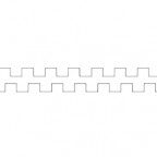
An AC voltage with constant frequency (in the range of 2 kHz to 10 kHz) excites the primary winding, which induces voltage in the two secondary (sine and cosine) windings. The induced voltages will have the same frequency as the supply, or reference, voltage, but because the two secondary windings are 90 degrees out of phase, the induced voltages in the secondaries will also be 90 degrees out of phase.
Image credit: Advanced Micro Controls, Inc.
The amplitudes of the induced voltages are proportional to the angular position of the shaft. Therefore, the shaft angle can be determined by taking the arctangent of the ratio of the sine voltage to the cosine voltage (sinθ/cosθ = tanθ). And because shaft position is determined only by the voltage ratio of the secondary windings, the position information is absolute, meaning the resolver can always determine the shaft position — even if it has been powered down and restarted — without having to move to a reference or index signal.
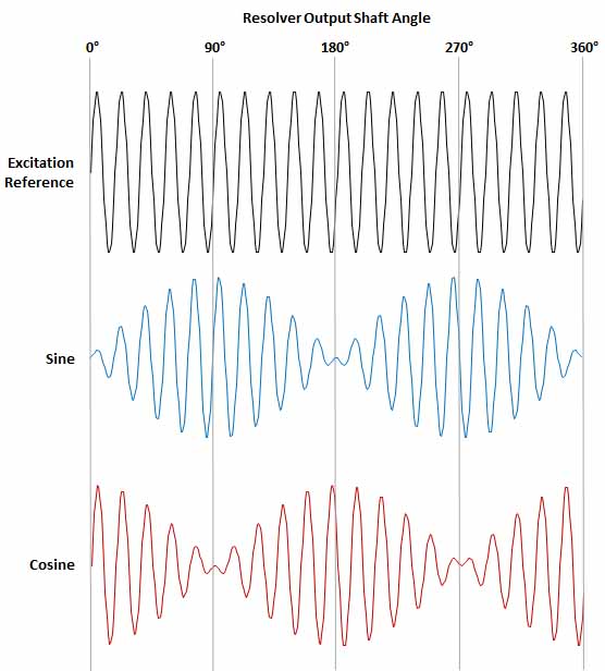
Image credit: Teledyne LeCroy
Note that no mechanical components, optics, or sensors are required for a resolver to work. This is the key to the resolver’s ruggedness. The electronics that convert the resolver’s analog output to a digital signal (sometimes referred to as an R/D converter) that the controller can accept are housed separately from the resolver itself. This means that contamination, vibration, extreme temperatures, and even radiation have little or no effect on the resolver’s operation.
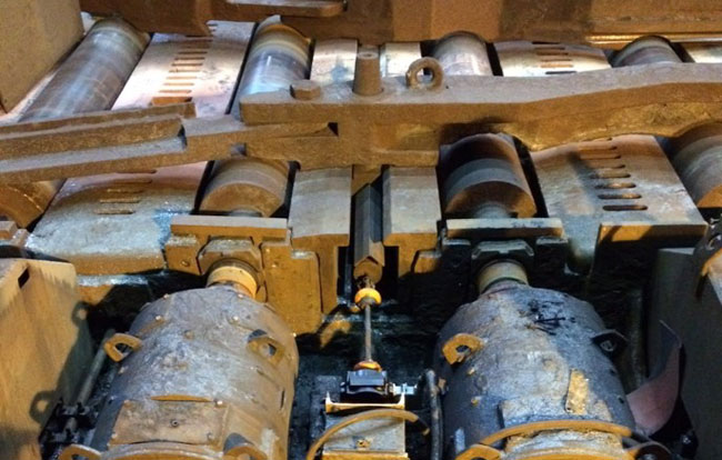
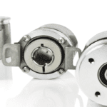
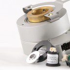
Image credit: Dynapar
Image credit: Nidec-Avtron
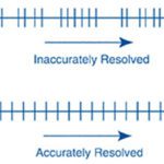
In theory, resolvers have infinite resolution, since every rotational position of the shaft is associated with a unique sine/cosine voltage. But signal conditioning — the R/D converter — limits both accuracy (typically in the range of 3-15 arcminutes) and rotational speed (typically 5000 rpm or less).
One way to achieve higher accuracy is to use a multi-speed resolver. In this design, the number of magnetic poles is increased, so each mechanical revolution creates multiple sine and cosine curves. The downside of multi-turn designs is that they lose the ability to provide absolute feedback. But there is a way to get absolute feedback and better accuracy from resolver set-ups — by mounting, or “stacking,” a single-speed resolver on top of a multi-speed resolver.
Feature image credit: Dynapar
Leave a Reply
You must be logged in to post a comment.