• Skip to primary navigation
  • Skip to main content
  • Skip to primary sidebar
  • Skip to footer

Motion Control Tips

Automation • Motion Control • Power Transmission

  • News
    • Industry News
    • Editor Blogs
    • Video
  • Controls
    • HMIs
    • PC-Based Controllers
    • PLCs + PACs
    • Stand-Alone Controllers
    • Software
  • Drives
    • Servo Drives
    • Stepper Drives
  • Encoders
    • Absolute Encoders
    • Incremental Encoders
    • Rotary Encoders
  • Mechanical
    • Bearings
    • Brakes + Clutches
    • Belt + chain
    • Couplings
    • Gears + Gearing
    • Lubrication
    • Shock + Vibration Mitigation
    • Springs + Rings + Seals
  • Linear
    • Actuators
    • Linear Motors
    • Linear Encoders
  • Motors
    • AC Motors
    • DC Motors
    • Brushless Motors
    • Gearmotors
    • Piezo Motors
    • Servo Motors
    • Stepper Motors
  • Systems
    • Conveyors + linear transport systems
    • Gantries + Stages
    • Rotary Tables
    • Grippers + End Effectors
    • Robotics
  • Networks
    • Connections + Sliprings
    • Fieldbuses
    • I/O
    • Sensors + Vision
  • FAQs
    • Motion Casebook
    • Motion Selection Guides
  • Suppliers
You are here: Home / FAQs + basics / What is AS-I Safety and what are its benefits for motion systems?

What is AS-I Safety and what are its benefits for motion systems?

February 19, 2021 By Danielle Collins Leave a Comment

When sensors, actuators, and other lower-level components are used in a functional safety capacity, AS-Interface Safety at Work offers a simple, efficient, bus network for monitoring these safety devices — alongside standard, non-safety devices — on the AS-Interface cable.


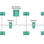
Recall that actuator-sensor interface (AS-Interface, or simply AS-I) is a master-slave bus that operates at the lowest level of the fieldbus hierarchy. It replaces parallel wiring for sensors and actuators with a single, 2-wire cable that transmits both data and power. Devices (also referred to as “nodes”) can be added anywhere along the cable and in any topology, such as line, ring, or star.

In some cases, these lower-level devices serve as key parts of a safety function within a machine, and as such, their communication with the master controller also needs to be “safe.”

AS-Interface has addressed the need for safe communication between safety components and higher level controllers with the creation of AS-I Safety at Work — a solution that allows safety devices to be connected on the same AS-I cable and fieldbus as standard (non-safety) devices.

Safety devices that have an AS-I Safety at Work interface can be connected directly to the AS-I cable. Devices that do not have an AS-I Safety interface can be connected via special interfaces, sometimes referred to as “coupling modules” or “adaptation devices.”

Not only does this solution take advantage of the simplicity of AS-I implementation, it also eliminates the cost and complexity of redundant infrastructure. And the safety concept can be easily modified as needs change. Safety devices can be added, moved, or replaced as needed with no restrictions on their implementation and no new wiring required.

AS-I Safety
The key to AS-I Safety at Work is a safety monitor, which monitors the safe devices and the correct operation of the network. The safety devices, such as e-stops and light curtains, work alongside standard (non-safe) devices on the AS-I cable and bus.
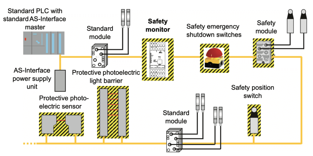
Image credit: Siemens

The key to AS-Interface Safety at Work is a safety monitor, which monitors up to 31 safety-related devices — such as e-stops, light curtains, and door latches — on the AS-I bus. Each safety device has a manufacturer-defined code table (a list of 4-bit binary numbers) which is stored by the safety monitor. When the master controller polls a safety device, the safety device transmits its status via a 4-bit code from its code table.

The safety monitor “listens” to this communication and compares the code sent by the safety device to the codes it has stored for that device. If the code is not listed in that device’s code table, or if there is a problem with network communication (such as an interruption or missing or delayed response from the device) the safety monitor switches off the relevant safety outputs, with a maximum reaction time of 40 ms.

AS-I safety
For more complex safety concepts, multiple safety monitors can be used on one bus to set up groups, or zones, of safety devices. These zones can be independent or they can be dependent on each other, and each safety device can be monitored by more than one safety monitor.
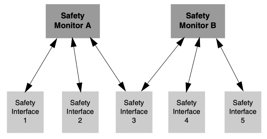
Image credit: Schneider

AS-I Safety at Work has been certified to meet functional safety standards PLe/Category 4 according to EN/ISO 13849-1 and SIL 3 according to EN/IEC 62061.


You may also like:


  • Part 4: Edge computing and gateways proliferate for industrial machinery

  • Part 3: Trends in Ethernet, PoE, IO-Link, HIPERFACE, and single-cable…

  • Part 2: Wireless in predictive maintenance — and wireless connectivity…

  • Part 1: Connectivity and IoT in motion and general automation

  • AS-Interface: What is it and when is it used?

Filed Under: FAQs + basics, Featured, Fieldbuses, Networking + IoT

Reader Interactions

Leave a Reply Cancel reply

You must be logged in to post a comment.

Primary Sidebar

MOTION DESIGN GUIDES

“motion

“motion

“motion

“motion

“motion

POWER TRANSMISSION REFERENCE GUIDE

RSS Linear Motion Tips

  • Haydon Kerk Pittman launches compact Z-Theta motion platform
  • Three easy ways to specify application requirements for linear motion systems
  • Sourcing linear motion solutions from NSK’s global manufacturing sites
  • Ride the wave of electrification: Off-highway designs with linear actuators
  • What are capacitive sensors and where are they used?
Subscribe Today

RSS Featured White Papers

  • Identifying Best-Value Linear Motion Technologies
  • Learn how to reduce noise and distortion in encoders’ signals
  • Helical Planetary Gearboxes: Understanding The Tradeoffs
Tweets from https://twitter.com/Motion_Control/lists/motion-control-tweets

Footer

Motion Control Tips

DESIGN WORLD NETWORK

Design World Online
The Robot Report
Coupling Tips
Linear Motion Tips
Bearing Tips
Fastener Engineering

MOTION CONTROL TIPS

Subscribe to our newsletter
Advertise with us
Contact us
About us
Follow us on TwitterAdd us on FacebookAdd us on LinkedInAdd us on YouTubeAdd us on Instagram

Copyright © 2021 · WTWH Media LLC and its licensors. All rights reserved.
The material on this site may not be reproduced, distributed, transmitted, cached or otherwise used, except with the prior written permission of WTWH Media.

Privacy Policy | RSS