Encoders and resolvers are used to track the angular or linear position of an object, such as a motor shaft (angular measurement) or a linear actuator (linear measurement). And with the addition of a clock signal, encoders and resolvers can also be used to measure the speed of the object.
A resolver uses a rotor with a primary winding and a stator with two secondary windings, phased 90 degrees apart. When voltage is applied to the primary (rotor) winding, it induces voltages in the stator windings. These voltages are equal to the reference voltage multiplied by the sine or cosine of the shaft’s angle from a zero point. The speed of the resolver (and of the shaft to which it’s attached) can be found by simply taking the rate of change of either secondary signal (the sine or the cosine signal).
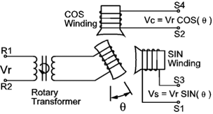
Image credit: Advanced Micro Controls, Inc.
Resolvers can generate a single electrical cycle per mechanical revolution (known as single-speed resolvers) or multiple electrical cycles per revolution (known as multi-speed resolvers). Speed measurement can be achieved with either design, although multi-speed resolvers provide more accurate speed information (at the expense of absolute position information).
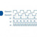
Encoders can provide either incremental or absolute position information, and those that supply incremental position can do so by using either square wave (TTL) signals (typically referred to as “incremental encoders”) or sine-cosine signals (typically referred to as “sin-cos encoders”). By analyzing the position information relative to a clock signal, any of these encoder types can be used for speed measurement. However, incremental (TTL) encoders are the most common design used for measuring speed — using either the pulse frequency or pulse period method.
Encoder speed based on pulse frequency
To determine an encoder’s speed based on the pulse frequency, the pulses (n) are counted for a defined amount of time (t). With the number of pulses per second (n/t) and the encoder’s pulses per revolution (N), angular speed can be calculated as:
![]()
ω = angular speed (rad/s)
n = number of pulses counted per time sample
N = pulses per revolution
t = time sampling period (s)
Or:
![]()
ω = angular speed (rpm)
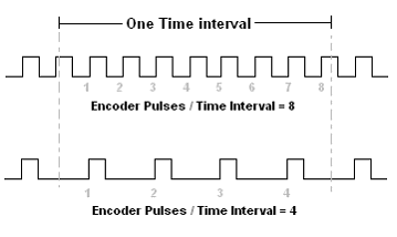
The pulse frequency method provides the average speed over a number of pulses, and can’t be used for very slow speeds, where few (or no) pulses may occur over the measuring time.
Encoder speed based on pulse period
To determine encoder speed based on the pulse period, the duration of each pulse — typically measured from the rising edge of one pulse to the rising edge of the next pulse — is timed using a high-frequency clock signal. The number of cycles of the clock signal (m) divided by the clock frequency (f) gives the duration for one pulse. With the number of seconds per encoder pulse (m/f) and the pulses per revolution, angular speed can be calculated as:
![]()
ω = angular speed (rad/s)
f = frequency of clock signal (Hz)
N = pulses per revolution
m = number of cycles of clock signal
Or:
![]()
ω = angular speed (rpm)

Image credit: Data Translation
The pulse period method of determining encoder speed is more precise than the frequency-based measurement. However, at high speeds, the frequency of pulses becomes very high, and the time between pulses may be too short for the counter to take accurate measurements.



Leave a Reply
You must be logged in to post a comment.