
A sine encoder is similar to an incremental encoder in design and function. Both devices measure either rotary or linear position changes and direction, and both are available with either optical or magnetic sensing technology.
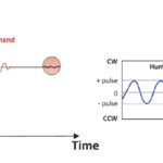
The primary difference between the two is that sine encoders supply position and direction information as 1 Volt peak-to-peak (1 Vpp) analog sine waves — typically termed “A” and “B” — in quadrature. Incremental encoders, on the other hand, provide position and direction information as a pair of quadrature digital square waves. This difference in output waveform allows sine encoders to supply significantly higher resolution than incremental encoders can achieve.
When two sine waves are in quadrature, one is actually a cosine. This is why sine encoders are also referred to as “sine-cosine” encoders.
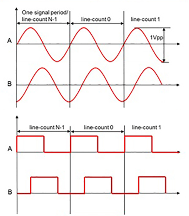
Image credit: Texas Instruments
Both incremental and sine encoders can use X4 encoding for a fourfold increase in resolution. For sine encoders, this is done by counting the number of zero crossing of the waveform per period. For incremental encoders, this requires counting both the rising and falling edges of both square waves per period. But because the sine encoder’s analog sine waves are continuous — not step functions, like the digital square waves of incremental encoders — the signals themselves can be broken down, or interpolated, into very fine counts to provide extremely high position resolution.
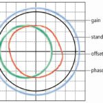
To mitigate the effects of noise, sine encoders can use a technique referred to as differential signaling, in which two complementary signals are transmitted on each channel. This technique is also used to mitigate noise in incremental encoders, although the analog signals of sine encoders are more susceptible to noise than the digital signals of incremental versions.
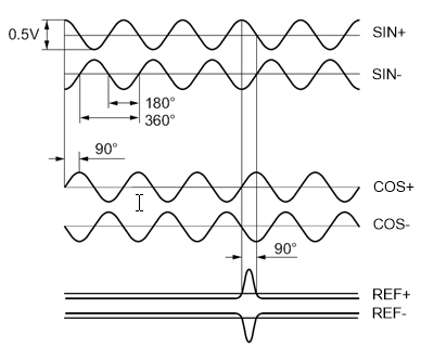
Image credit: Ingenia
These complementary signals — often termed “A-,” B-,” and “R-” — are the same as the primary signals, but with a 180 degree phase shift. Because any noise on the signals is the same (referred to as “common mode” noise), taking the difference of the two signals eliminates the noise but preserves the signal waveform.
Incremental or absolute?
Like incremental encoders, sine encoder output can include a reference signal — often termed “R” or “Z.” The reference signal has a slightly lower amplitude than the A and B signals, and its peak occurs only once per encoder revolution. Some manufacturers tout sine encoders with a reference signal as “absolute” encoders, but in fact, they can only provide absolute position information within one shaft revolution. The reference signal, however, is beneficial during startup and, in some cases, for commutation purposes.
High resolution for better servo control
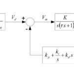
Sine encoders are often used on servo motors, where higher feedback resolution is a benefit for the position and velocity control loops. In the velocity loop, high resolution improves velocity control and allows higher gains to be used in the control loop with lower noise. Higher gains also provide better system stiffness and better resistance to disturbances. In the position loop, higher feedback resolution provides better repeatability and reduces noise.
One limitation in the application of sine encoders is the frequency of the encoder output versus the bandwidth that the receiving electronics can process. The output frequency is determined by the encoder’s line count and mechanical speed, and when a sine encoder with a very high line count is operated at high speed, the output frequency of the encoder may exceed the bandwidth that the drive or controller can process.
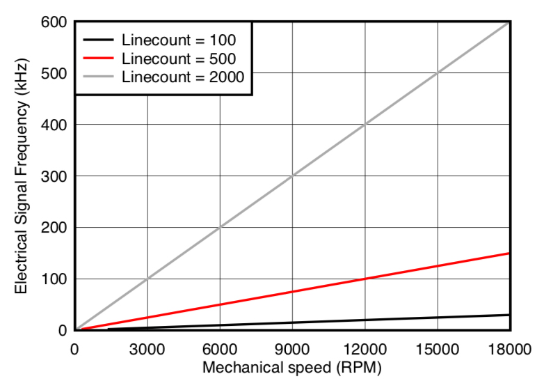
Image credit: Texas Instruments
Leave a Reply
You must be logged in to post a comment.