
Electrical and controls engineers are normally tasked with selecting and integrating the electronic components that go into a motion control system, such as motors, drives, controls, feedback devices, and HMIs. In doing so, their primary concerns tend to be on making the various components communicate with each other, working through complex equations for drive tuning, and programming HMIs to ensure the user can operate and troubleshoot the system with relative ease.
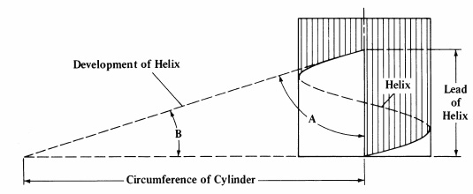
And while some of these tasks require a fundamental knowledge of mechanical principles – particularly torque, speed, and inertia – rarely do they go into the nuances of how linear guides and drives (ball screws, belts, rack and pinions) work and their impact on the electrical side of the system. But even if you never have to size or select them, it’s helpful to understand the basic principles and equations for linear motion components that are common in motion control systems.
L10 bearing life – Bearing life (or L10 life) is a fundamental concept for sizing any recirculating bearing. This article explains what L10 life is and how to calculate it.
How to calculate move profiles – The type of move profile an application uses determines the maximum speed and acceleration, which affects motor sizing and drive tuning. This tutorial describes the two most common move profiles and how to calculate velocity and acceleration for each.
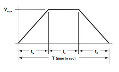
How to calculate acceleration – More information (and equations) specifically dealing with acceleration.
How to calculate drive torque for ball screws – Continuous and intermittent torque values are key to motor sizing. This article explains how to calculate torque during constant speed, torque during acceleration, and torque during deceleration.
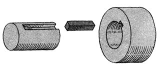
Torque considerations for keyed shafts – This article demonstrates the disparity between the torque that can be transmitted by a solid shaft versus a keyed shaft, including equations for calculating when shear failure and crushing failure will occur.
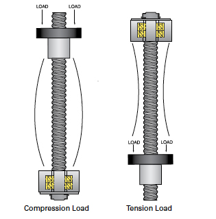
Ball screw back driving – Screws are often used in vertical applications because they prevent the load from catastrophically crashing if the motor loses power. But if the load is too heavy, it can still cause the screw to back drive. This application note provides equations for calculating back driving torque.
Ball screw buckling – When a screw is used in a vertical application, it’s important that the load doesn’t exceed the column strength of the screw, which depends on the screw length and the end bearings used. This tutorial explains why buckling occurs and how to calculate the buckling load for a given screw.
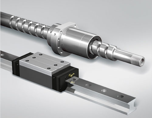
If you’re new to linear guides and drives, you may also want to check out the linear guide and ball screw glossaries. They include descriptions of each technology, including technical specifications and details on construction.


Leave a Reply
You must be logged in to post a comment.