
Servo systems typically use a combination of three types of control loops: current, velocity, and position. The velocity control loop serves two purposes—it enables the system to respond to changing velocity commands, and it allows the system to resist high-frequency load disturbances. But the velocity loop by itself can’t ensure that the system maintains a given position over long time spans. This is why velocity control loops are often used in conjunction with position control loops in a cascaded structure.
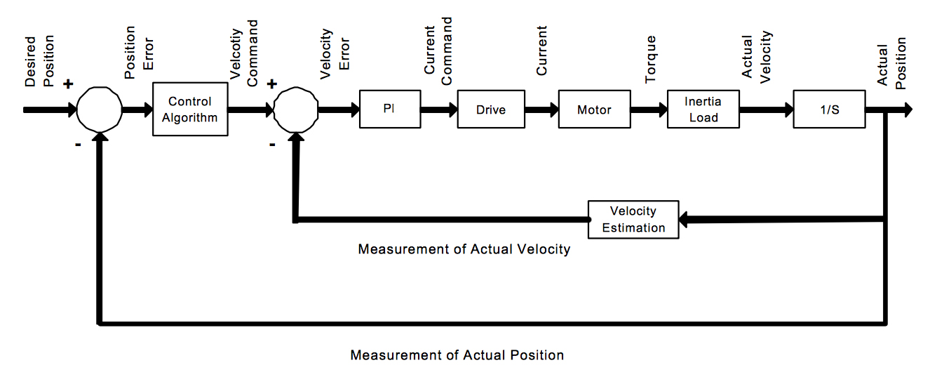
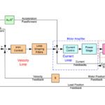
Image credit: Integrated Industrial Technologies, Inc.
The velocity controller is typically a PI controller, using the proportional, Kvp, and integral, Kvi, gains, whereas the position controller typically uses only the proportional gain, Kp. (Note that the current control is often set automatically and is manually adjusted only in rare cases.)
To recap from a previous post, proportional gain has a value that is directly proportional to the error and determines the voltage that is applied to overcome the error. Proportional gain is related to system stiffness.
Integral gain accumulates the error over time and provides a restoring force during the end of a move to push the system to a point of zero error.
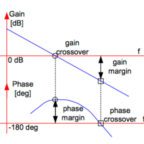
In cascaded control loops, the bandwidth of the inner loop should be anywhere from 5 to 10 times the bandwidth of the outer loop, or the inner loop will have little effect on the outer loop. Best practice is to tune the fastest loop first, so in the cascaded position-velocity loops, we start with the (inner) velocity loop.
Since the velocity loop is a PI controller, there are only two parameters to tune—Kvp and Kvi. For the move profile, use a medium-value velocity target (not the lowest or the highest that the application will experience), but keep the acceleration rate relatively high. This will magnify the effects of the system’s response, making it easier to tune the system.
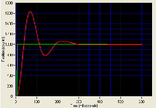
To begin the tuning sequence, increase the velocity proportional gain (Kvp) to a point just before overshoot occurs. (It is sometimes helpful to increase Kvp to the point of overshoot, and then back it down until overshoot is eliminated.) Now increase the velocity integral gain (Kvi) until a small amount of overshoot (5 to 15 percent) occurs.
In cascaded control loops, the performance of the inner loop affects the performance of the next outer loop. In essence, the inner loop (velocity) acts as a low-pass filter to the outer loop (position).
Once the velocity control loop is tuned, the controller should be set to operate in position mode, and the position loop can be tuned. Begin with a low value for the position gain (Kp), and raise it slowly, to a point just before overshoot occurs.
Now that the velocity and position gains have been set and stabilized, increase the target velocity and test the gains again. Adjust them if needed, to make the gains suitable across the full velocity range of the application.
It’s important to note that the output of the position loop is a velocity command. Here’s how it works: The position error detected by the position loop is scaled by the position gain, Kp, to generate a velocity command. That velocity command is sent to the velocity loop, which uses it to command more torque, which moves the motor to correct the position error.
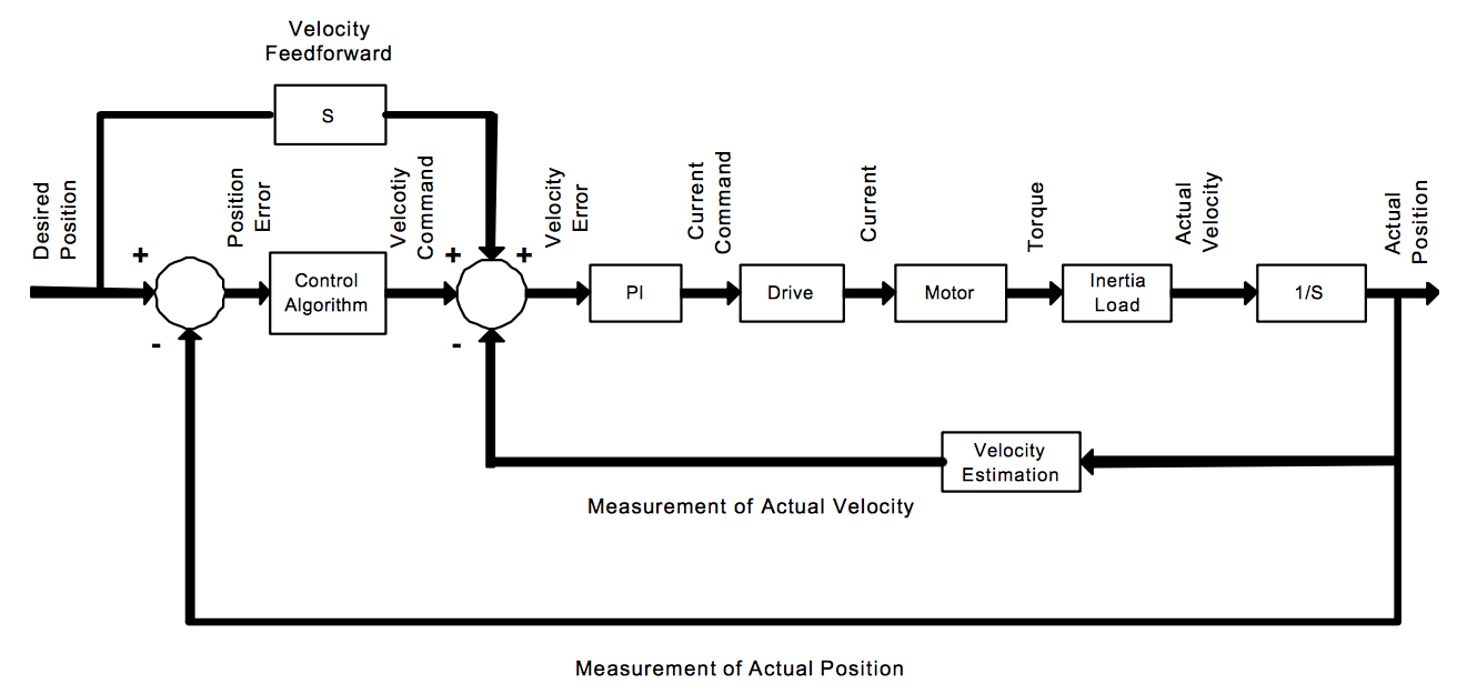
Image credit: Integrated Industrial Technologies, Inc.
If the application requires very low following error, it may be necessary to add feed-forward control to the tuning parameters. Velocity feed-forward control (Vff) takes a proactive approach, calculating the velocity needed to meet the desired position and feeding this value directly to the velocity control loop, rather than allowing the control loop to wait for the position error to develop. However, the drawback of using velocity feed-forward is that the position loop proportional gain (Kp) must be lowered, which reduces the system’s stiffness.
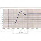
Feature imaged credit: National Instruments

Leave a Reply
You must be logged in to post a comment.