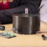
In a recent video recorded at the Design World studios, I teamed up with my colleague Paul Heney to review the features of a brushless-motor drive from Koford Engineering in Winchester, Ohio.
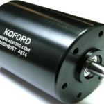
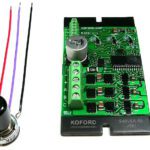
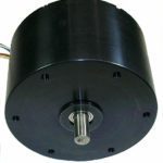
Consider some examples from Koford Engineering, which sells a full line of compact 5, 10, 15, 20, 30, and 40-A brushless motor drives. These drives pair with slotless motors or other low-inductance brushless motors and need no external inductors. One variation is detailed at motioncontroltips.com/hall-drives-brushless-motors. The control board provides electronic commutation, speed control, current limiting, direction control … and delivers tachometer output of three or six pulses per revolution with no added components (such an encoder) needed.
The control boards are preprogramed so need no user setup or adjustment. They run at 100% duty cycle. That contrasts with most brushless drives, which are limited to 95% and can’t get full rated motor performance. Part numbers are available from Koford for speeds to 200,000 rpm for two-pole motors … or 100,000 rpm for four-pole motors. There are both two and four-quadrant versions. For four-quadrant units (electrified by a power supply and not a battery) braking modules are available to absorb regenerated energy. This eliminates the need for a relay and resistor for energy absorption.
Open and closed-loop versions are available. In standalone operation, there’s an optional speed pot. For digital operation, the drive can connect to a microcontroller of 5 V or 3.3 V with a 5-V interface.
Speed input is with a 0-to-5-V analog input (of less than 1 mA). Otherwise, speed input is through a 100 Hz to 100 kHz square wave with variable duty cycle. To run an application that goes in a single direction — as in a pump or beam chopper — all the drive needs is connection of power, the three motor leads, and the 0-to-5-V speed input or speed pot. If the application needs reversible operation, a SPDT switch can be added between P- and DR. Otherwise a 0 or 5-volt signal from a microcontroller to DR works.
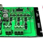
The motor-drive sample we got accommodates a potentiometer with leads that connect to three terminals labeled P. The power supply connects to the plus and minus, and motor windings connect to A, B, and C here. As mentioned, the drive can be controlled with a speed pot, a 0 to 5-V analog signal, or a PWM signal. Users can also program the drive to run at a fixed speed with only power and ground and motor connections.
Any thermistor output from a Koford motor connects to the temperature interface and shuts the motor off if a winding temperature exceeds 130°C — and turns the motor back on when that temperature falls below 100°C. The objective is to prevent the winding temperature from exceeding 150°C but the manufacturer sets the shutoff temperature at 130°C to provide a little bit of margin. These drive connections can be left open if the motor with which it’s pairing doesn’t have temperature sensors.
The best setups mount the drive to an aluminum chassis or frame or heat sink. Drives get hottest under high currents, low duty cycles, and continuous operation. Heat sinks are probably unnecessary if the application runs at 100% duty cycle with normal indoor ambient temperature; if current is low compared to rated current; or if the application is intermittent with on and off times of a about a minute or longer. For hot environments, forced-air cooling directed at the board is useful. For long-term reliability, it’s best to prevent the hottest spot on the board from exceeding 100° C — verifiable with a portable infrared thermometer.


Leave a Reply
You must be logged in to post a comment.