What applications need quiet gearmotors? The answer might surprise you — because the human ear can detect noise at 10 dB lower than ambient levels, and many gearmotors operate in close proximity to people. In this technical article, we outline recent staff engineers’ research and development into the problem (and potential solutions for) gearmotor noise.
 By Gabriel Venzin, President | ABM Drives Inc.
Sound is the back-and-forth vibration of particles in a medium created when a traveling wave passes through the medium. Noise is undesirable sound. Sound pressure is defined with logarithms that compare sound pressure to the decibel (dB) sound pressure standard of 0.00002 Pa = 20 µN/m2 near the lower limit of human audibility. One decibel is one tenth (deci-) of one bel, named in honor of Alexander Graham Bell.
Gearmotor noise isn’t just a gear problem — it’s a system problem. Physical interactions between gears can excite system dynamics, so most gear noise doesn’t originate from the gears. Gear whine is created by the gears as they mesh and is amplified by resonances in the housing’s ribs, beams, and sides. Gear rattle is a sound that is excited by the driving source such as the electric motor. Each gear has its period of rotation and so a unique fundamental frequency.

Why design quiet gearmotors? Consider where gearmotors must operate in public spaces. Here, motion control in churches, libraries, auditoriums and theatres need quiet gearmotors for curtains, podiums and stages that need to rotate, lift or slide, unnoticed by the audience.
In contrast, military equipment needs quiet gearmotors for stealth operations. Medical equipment benefits from quiet gearmotors for increasing patient comfort and assurance. Residential settings — for example, in biomass heating systems — benefit from quiet gearmotors as well. Here, stored wood chips or pellets in a silo must be conveyed to a boiler by an auger via a motor-driven rotary feeder — and ash removal is accomplished the same way.
Gearmotor basics: Functions and today’s design process
A gearmotor delivers high torque at low speed. It’s a combination of a gear reducer and an electrical motor. In short, gearmotors take motor power and reduce its speed while magnifying its torque. The two most important factors at the gearmotor output shaft are rpm and torque. So once the input-torque requirement is known, the next step is to calculate the needed motor-input horsepower.
The gear train inside a gearmotor multiplies torque from the motor side to the output shaft. This is the gearbox ratio and is the number that determines the torque multiplication from input. 30:1 means that the output torque is 30 times the input, not accounting for internal efficiency losses.
A right-angle or parallel-shaft gearbox can combine with permanent magnet dc, ac induction, or brushless dc motors. Advanced gearmotor technology includes the use of new materials, coatings, bearings, and gear tooth designs optimized for noise reduction, strength and longer life, in smaller spaces.
Gearmotor designs are for specific operating conditions and load ranges. So at the start of a machine build with known problems or opportunities for improvement (including possible economic gain or improvement in how personnel or users perceive the gearmotor) consider the motion components and features (including gearmotor options) that might work. Then narrow down the options to feasible alternatives. Next identify those with the best balance of performance and economics to reach a design target. Finally, integrate the most feasible, risk-reduced, and economically viable features and capabilities into products with both form and function.
Such a design approach is now easier than ever. In the past, designs often started with mechanical engineers and then passed to the team’s electrical engineers and finally onto the control engineers. By the end, all the flaws were baked into the design. In contrast, today the standard is integrated design supported by mechatronic modeling. But with holistic design approaches, engineers must understand the accuracy requirements of the entire electromechanical system. Another caveat is that control system, drives, and gears and mechanical linkages must be carefully chosen to leverage all the components’ full capabilities. That necessitates a design approach that starts from the drive back to and including the motor.
More thorough and detailed design objectives boost the odds of project success. So keep the motivation behind the project top of mind and allow that motivation to guide engineering decisions. The goal is to have a system to serve humans and not the design itself. The old adage, “You’ll never get there if you don’t know where you’re going” certainly applies to the design process.
One indispensable tool in engineers’ arsenal — especially in the work of making machine builds as quiet as possible — includes simulation to optimize proposed designs. Such software can reduce overall design time by as much as 75%. In the case of gearmotors, 3D models and associated data help engineers analyze and virtually build and inspect their gearmotors — and completely define the assembly to improve quality, manufacturing techniques, and procurement.
Noise generated when gears engage
Selecting gears and motors is a science. Even suitable gears make noise. Complicating matters is that gear noise comes in many types. To solve gear-noise problems, the first step is to determine the type of noise that is objectionable. What’s considered gear noise depends on the speed of operation. Use qualitative and quantitative terms to describe how design factors and manufacturing mistakes play into the noise equation. Then discuss with the design team (and potential suppliers) the problems of gear noise, dynamics, measurement, and modeling.
Another starting point for gearbox design is to define a service factor — including hours per day and shock or vibration requirements. A gearbox with an irregular shock profile (as in a military design, for example) requires a higher service factor than a gearbox that runs intermittently.
Gear noise is generated by tooth-to-tooth load transfer that causes pressure-pulse trains radiating through the gearset and motor housing. The noise’s frequency is the product of gear rotational speed and the number of gear teeth. Most types of gear noise occur at tooth mesh frequency or harmonics in the audible range. That said, noise can also occur as a low-frequency modulation of the higher tooth-mesh frequency noise. This results in a phenomenon called sidebands.
Gear noise can be very annoying — even when it isn’t the most significant noise source. That’s because it occurs as pure tones that the human ear can detect even at 10 dB lower than the overall noise level.
The asymmetric gear noise spectrum arises from amplitude and frequency modulation of gear-mesh excitation produced by low-frequency manufacturing and assembly errors. Gearmotor sounds from gear mesh, bearing rotation, lubricant movement, motor vibrations and interaction of the housing all contribute to the overall sound generated.
Vibration tendencies can be minimized with high-quality helical gearing and optimized gear engagement.
Helical teeth engage gradually over the tooth faces for quieter and smoother operation than spur gearsets and have higher load capacities.
Shuttling force is the side-to-side oscillation of the tooth mesh force along the profile as the tooth pair undergoes the engagement process. The oscillating force can cause dynamic excitation to the gearbox system. Since it occurs at the mesh frequency, it contributes to the gear noise response. With double helical gears, this axial force is eliminated.
The tooth finish contributes to the sound generated. Helical gearing that has only been hobbed is louder than helical gearsets that have been shaved or ground to remove rough tooth-surface finishes that hobbing generates.
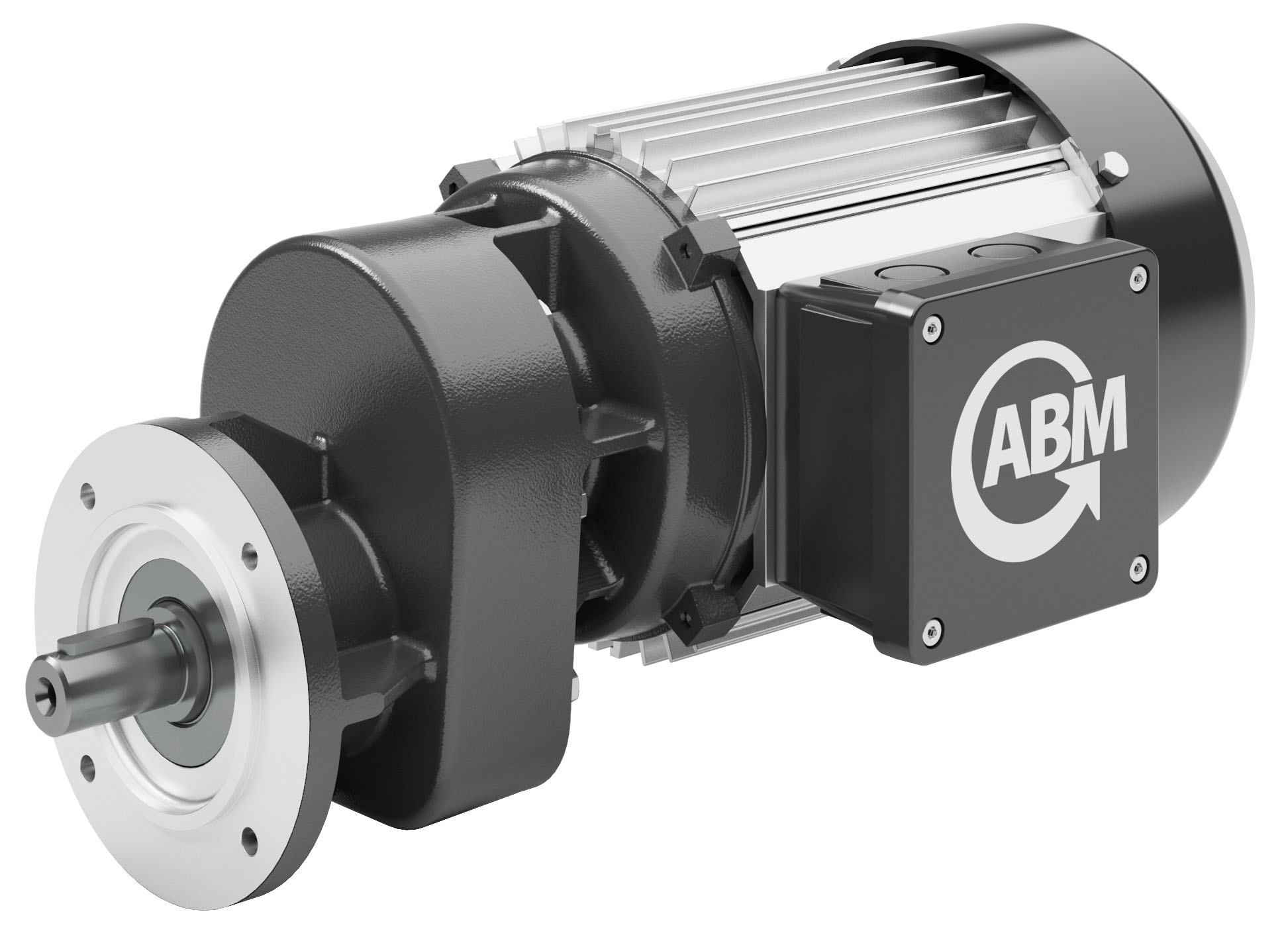
Use noise optimized gear geometry to minimize the impact of individual gear engagement impulses.
Designing and analyzing gears as a system lets engineers improve and optimize microgeometry for the reduction of gear noise.
Pitch: A gear system with normal pitch of the driving gear a very small amount larger than the normal pitch of the driven gear delivers more silent transmission. Minimum noise requires a contact ratio smaller than 2 or 1. Even under a slight load, the influence of torsional stiffness is important.
Contact ratio: The gear contact ratio is the average number of teeth in contact. It usually varies between 1.2 on the low end to 1.8. Spur and straight bevel gears with operating contact ratios under 2.0 create more noise than gears with larger contact ratios. Helical and spiral bevel gears have total contact ratios well above 2.0 and produce less noise.
A smooth, quiet and higher speed gearset may have more teeth, finer diametrical pitch, lower angle pressure, and a higher contact ratio. Changing one of them can change many of the other design elements. Optimizing the entry and exit points of gears reduce vibration, noise, sliding friction and heat generation. All gear designs are a compromise to reach the target results.
It’s clear then why quiet gearing must be very precisely manufactured. High-quality gearing guarantees quiet operation. With high precision manufacturing, gear noise can be cut from an average level of 82 dB to 77 dB measured 300 mm away from the pitch point.
Torsional modes may be excited by low order harmonics of shaft rotation; the magnitude of excitation is directly related to gear machining errors.
No matter the design, make the normal pitch difference as small as possible. The profile form error should be as close to the theoretical involute as possible. The key is in the finishing method after hardening to ensure final accuracy.
Also keep in mind that it’s impossible to eliminate all gear noise, because it’s impossible to cut perfect gears. Even if one could, it’s impossible to limit the effect of system dynamics. One can only minimize and control gear noise to the extent that it won’t be considered problematic or audible.
Minimize gear noise in high-speed stages by fine machining and grinding. Gearmotor rotation speed plays a significant role in noise generation. There’s very little difference between a hobbed-only gearset rotating at 30 rpm versus a ground-finished gearset. But at higher gearset speeds they exhibit a more noticeable sound difference. During gear manufacturing, hobbing is a roughing operation that produces smooth and accurate gear teeth. Shaving and hardening are finishing operations improving dimensional accuracy, surface finish, and hardness. Shaving removes small amounts of material to correct profile errors. Final grinding operations produce a high surface finish, correcting any distortion following heat treatment. Precision ground gearing provides for low noise and extended life.
Quiet operation requires minimal gear backlash. Backlash is clearance between mating gear teeth and should be enough to allow lubrication film between the teeth. The easiest way to reduce backlash is to shorten the distance between gear centers with low or even zero clearance. Such an approach lessens variations in center distance, tooth dimensions, and bearing eccentricities.
Variables such as manufacturing errors, mounting tolerances, and bearing play often increase backlash in a gearmotor. Precision gearmotors minimize such imperfections by incorporating close-tolerance parts. Typically, they combine hardened precision gears, quality bearings and machined housings with close tolerances.
To minimize noise, all gearbox components should be optimally tuned to each other. Three types of gear tooth transmission errors are spacing errors, random errors, and elastic deformations, which combine with mean profile deviations. Gear resonance can be reduced by identifying excitation mechanisms; using finite element analysis to determine the natural frequencies of individual gears; eliminating torsional modes from operating range; detuning and damping helical and bevel gears; and identifying remaining resonant problems with other elements of the gearmotor such as housings and accessories.
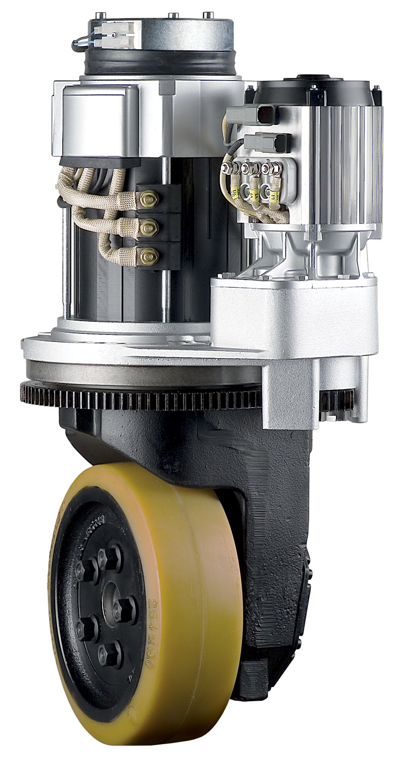
Vibration is generated at the gear mesh because of time-varying mesh stiffness, manufacturing errors and assembling errors. This vibration is transmitted to the housing through shafts and bearings. The radiated noise is induced from the vibration of the housing. Because geabox vibration and noise significantly degrade performance of gear transmission, the prediction and control of gearbox vibration are paramount to design output-motion reliability as well.
Simulate the radiated noise of a gearbox using software that uses the finite element method (FEM) and boundary element method (BEM). Such software helps identify the assembly’s mode order and which housing sides make the maximum acoustic contributions. Here, one solution for especially noisy portions of the housing is to add ribbing to reduce the radiated noise.
Reduce natural resonance by optimizing housing designs with ribbing and non-symmetrical components — especially on parallel-shaft gearbox types. Motor housing and gearbox covers should be single die-cast components to eliminate the tolerances on motor-gearbox interfaces (a common problem area for noise and vibrations). They should harmonize ideally with each other.
Depending on housing design, parting lines can fall on the top or bottom and be stepped or angled. For silencing, trimmed and precisely machined aluminum die-cast housings additionally reduce noise emissions. Tight-fitting housing covers and flanges prevent distortions that can amplify noise. Aluminum housings absorb harmonics and other vibrations better than cast iron.
Even a 10% increase in wall thickness can boost stiffness by 33% or so. But adding ribs, corrugations, and curves to die-cast housings keeps material costs low while maintaining rigid strength and durability — even in assemblies with thinner housing walls.
Effective rib arrangement positions are in arcs on the panels with large acoustic contributions. The ribs are effective when placed along the lines from the effected location to the nearest fixed points of the housing. Arranging ribs on the housing surface is one of the main techniques to stiffen the gearmotor housing.
Next to metal selection, maintaining uniform wall thickness is critical. Wall thickness is a balance between strength and weight. Wall thicknesses dictate the consistent flow and thermal properties during the die-casting process.
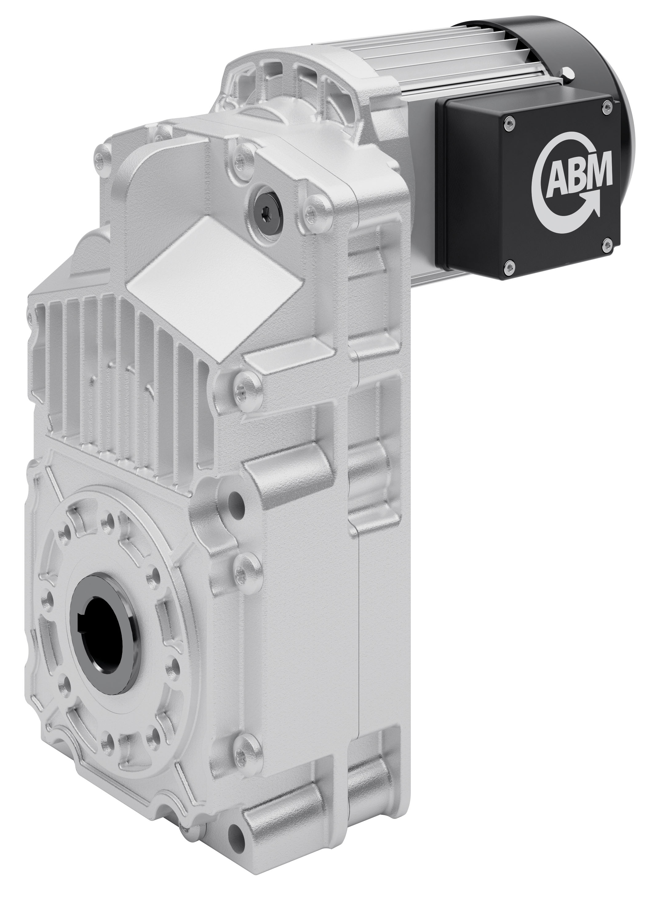
Size, geometry and wall thickness requirements have an impact on tolerance. Thicker walls produce larger shrink rates depending on the material. Generally speaking tight tolerance parts for die casting is ± 0.002 inches. Many factors influence the design here — including materials, part complexity, tooling, and the die-casting process itself.
Excitation from the motor’s electromagnetic field can transfer to the rotor, so look for motor rotors that are sturdy and robust. Stator magnetic forces vibrate the rotor as any ring when struck. The stator vibrates in one or more of its flexural modes; models represent the core as a beam supported on both ends and flexing due in response to applied forces.
Analysis demonstrates that vibration arises from electrical imbalance or mechanical unbalance (in the motor, coupling, driven equipment); mechanical effects (in the form of looseness, rubbing, and imbalanced bearings); external effects (in the base or driven equipment or from misalignment); and excitation of critical resonance speeds. Tip: During analysis, list all possible causes for the frequencies under examination. Then eliminate the causes one by one until all that remains is the true source of the problem.
Key to quiet operation is high-quality rotor balancing. All types of rotating machinery need balancing at operating speed. Rotor balance involves the entire structure — shaft, rotor laminations, end heads, rotor bars, end connectors, retaining rings, and fans. Only careful control of the design and manufacture of these motion components ensures stable and precise motor balance.
If the motor’s operating speed coincides with the housing resonant frequency, amplification will occur. The only option is to change the resonant frequency of the housing — usually by changing the stiffness or weight of the gearset, housing, or motor.
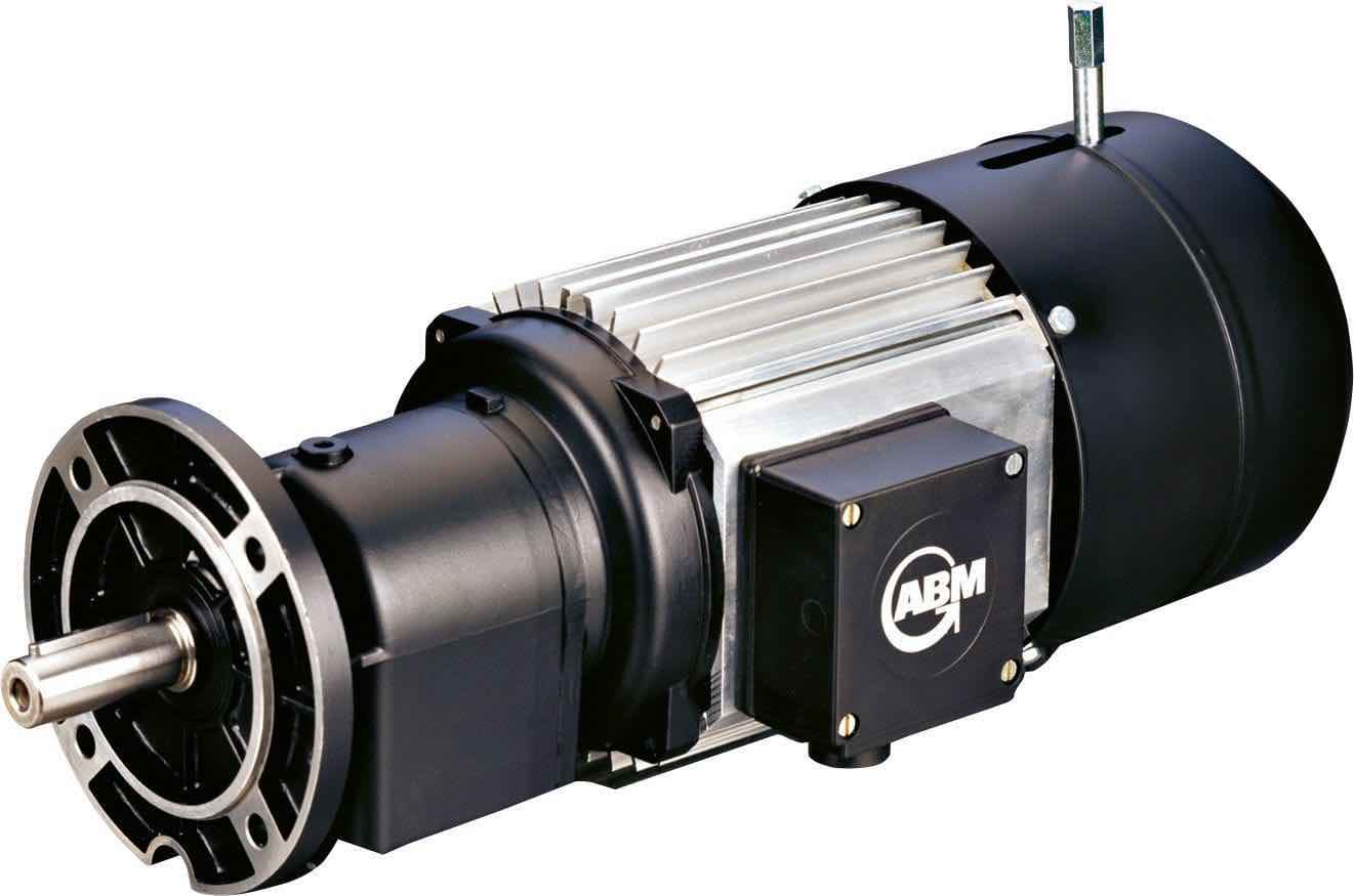
When choosing manufacturing partners during a machine build, remember that there are two methods for choosing a gearmotor. One is selecting a pre-engineered unit and the other is choosing a gearbox-motor combination and integrating them into the equipment.
Pre-engineered gear solutions are suitable if a design engineer doesn’t have the time or engineering resources to build a gearmotor in-house — or if the design needs a quick setup. New modular approaches to support OEMs (and enable new machine tools, automation, and design software) now let engineers get reasonably priced gearmotors even in modest volumes.
It’s true that one benefit to selecting a separate motor and gearbox and then combining them can less expensive than choosing a pre-engineered gearmotor. Another benefit to this approach is that one may be able to design the most optimized gearmotor for the application at hand … because this approach also gives the design engineer the most control over the final configuration and cost.
No matter the approach to gearmotor selection, be sure to continually improve the design by comparing predictions of noise with measurements of noise by using spectrum analysis. Then use the result of the analysis to improve next gearmotor iteration.
ABM drives | www.abm-drives.com
About the author: Gabriel Venzin is President of ABM Drives Inc. ABM Drives U.S. headquarters are in Loveland, Ohio. Call Venzin at (513) 576-1300 or email gabriel.venzin@abm-drives.com.



Leave a Reply
You must be logged in to post a comment.