There are two forces in piezo motor operation that are often confused: stall force and holding force. The stall force is the maximum force a motor can hold while running (i.e. in a dynamic state) before stalling occurs, while the holding force is the maximum load a motor can hold while powered-down (i.e. in a static condition). In many cases, the holding force of a piezo motor will be greater than the stall force, by about ten percent.
One of the most common piezo motor designs is the ultrasonic piezo motor, which operates by means of a pusher, or friction tip, attached to a piezo-ceramic plate, with an electrode on each side. When either electrode is excited, it produces high-frequency eigenmode oscillations, which means that all parts of the system move sinusoidally at the same frequency. The pusher, therefore, moves at the enigenmode frequency along an inclined linear path. This drives the mechanical part of the motor, either a slider or table, with both a longitudinal and a transverse component to the motion. It is the transverse component of the movement that determines the maximum frictional force and the holding force of the motor.
The holding force is ruled by the Coulomb friction. Coulomb friction is the force, exerted by two surfaces on each other, that does not allow motion. Because it prevents motion, the Coulomb friction must be less than the product of the coefficient of friction between the surfaces, and the normal force that the surfaces place on each other.
Fs = μs*N
Fs = Static friction force (N)
μs = Coefficient of static friction
N = Normal force between the surfaces (N)
If the Coulomb friction is greater than the coefficient of friction times the normal force, then motion will be induced. In other words, if a block with mass of 20 kg rests on a surface with a coefficient of friction of 0.1, then Coulomb friction must be less than 19.62 N. Otherwise, the block would move.
Fs = 0.1 * 20 kg * 9.81 m/s2
Fs = 19.62 N
The ability of piezo motors to produce a holding force or torque when there is no input power rules out the need for an external brake. It also reduces power consumption and eliminates heat build-up, which is a benefit for applications that are sensitive to temperature stability. One application where these benefits are realized are pinch valves, which have traditionally been controlled with solenoids or pneumatics. When operated with piezo motors, both reliability and energy efficiency are increased, since no energy is required in the hold position, and the valve remains shut without consuming power.
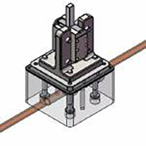
Image credit: PiezoMotor AB
Another application that benefits from the power-off holding force of piezo motors is the picomotor actuator. These tiny actuators use a threaded jaw clamped to a small screw. Each end of the jaw is connected to one end of a piezo motor. As an electrical signal is applied and changes the length of the piezo, the jaws slide in opposite directions, causing the screw to turn. Picomotors are used in semiconductor processing and wafer inspection equipment, which require high resolution along with the ability to maintain positions in the nanometer range with no applied power.
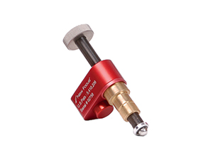
Image credit: Newport Corporation


Leave a Reply
You must be logged in to post a comment.