Variable frequency drives are made up of three primary sections: a rectifier, which converts the supplied AC voltage to DC; a DC bus, which stores the DC voltage; and an inverter, which converts the DC power back to AC at the voltage and frequency required by the motor.
The most common, and simplest, rectifier designs use diodes, with each phase of power requiring two diodes, one that allows current to pass through when voltage is negative, and one for when voltage is positive. Therefore, a 3-phase system requires six diodes to make up the rectifier. This design is commonly referred to as a 6-pulse rectifier because it draws current from the AC source in six pulses. And because the current draw from the power supply isn’t a smooth sinusoidal waveform, the VFD is considered to be a non-linear load.
This non-linear current draw can distort the supplied AC power, causing problems for motors and other electronic equipment. The amount of distortion depends on the capacity of the supply circuit. If the rectifier represents a large percentage of the available capacity of the supply, then distortion can be substantial.
Distortion can be modeled as additional voltage waveforms in multiples of the fundamental (i.e. 60 Hz) voltage. These additional waveforms start at a multiple of 5, but (for 3-phase systems) skip all multiples of 3. This is known as harmonic distortion, and for typical 60 Hz systems, the 5th, 7th, 11th, and 13th harmonics are most prevalent.
The measurement of harmonic distortion is referred to as total harmonic distortion (THD):

Where:
Ih = magnitude of the voltage harmonic component or the current harmonic component
I1 = magnitude of the fundamental voltage or the fundamental current
With the 6-pulse rectifier described above, the 5th and 7th order harmonics are significant, and filtering is often needed. One way to reduce THD in an AC drive is to use a 12-, 18-, or even 24-pulse rectifier.
Harmonic current in a motor increases hysteresis losses and eddy current losses. These losses raise the motor’s operating temperature, which can derate performance and reduce the life of the motor.
A 12-pulse rectifier uses two 6-pulse rectifiers in parallel (12 diodes) to feed a common DC bus. A transformer with one primary and two secondary windings creates a 30 degree phase shift between the two current waveforms, which eliminates the 5th and 7th harmonics and reduces current THD to between 10 and 15 percent. Disadvantages of a 12-pulse rectifier are cost—due to the special transformer required—and physical footprint.
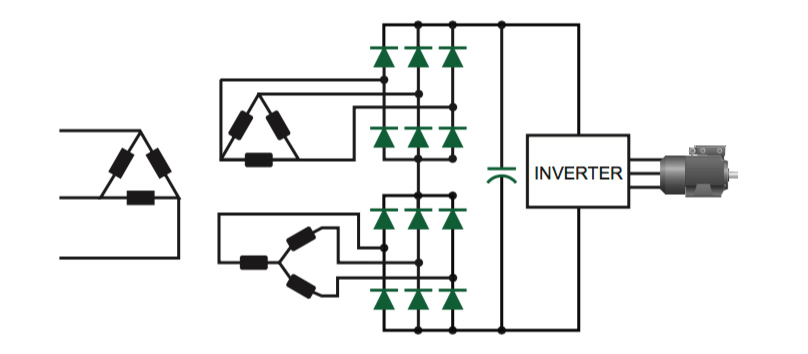
Image credit: Emerson Industrial Automation
Similarly, an 18-pulse rectifier uses three 6-pulse rectifiers (18 diodes) and a multi-phase transformer with one primary winding and three secondaries. The multiple windings work to offset the voltage waveform by 20 degrees. This cancels the 5th, 7th , 11th, and 13th harmonics and provides a current THD in the range of 5 percent. But as the transformer becomes more complex and additional rectifiers are added, cost and footprint further increase.
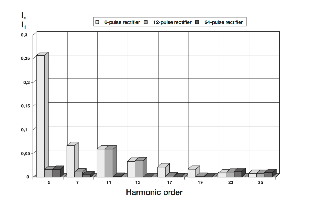
Image credit: ABB
Eliminating virtually all harmonics requires a 24-pulse rectifier, which consists of two 12-pulse rectifiers in parallel and two 3-winding transformers. The transformers provide a voltage waveform offset of 15 degrees, which cancels most low-frequency harmonics. However, the high cost of a 24-pulse rectifier makes it practical only for very high-power drives or for large multi-drive systems.



Leave a Reply
You must be logged in to post a comment.