
 It’s expensive to keep equipment perfectly balanced, and it’s often inefficient to add structural reinforcements. But adding wire-rope isolators is a cost-effective way to address vibration — and when done upfront, it can save machine structures from fatigue. In the video below, I join my colleague Mary Gannon to review several wire-rope isolators from ITT Enidine and where they make the most sense.
Vibrations damage machines and electronics, so designs often incorporate wire-rope isolators, air springs, or elastomers — but elastomers only attenuate noise and vibration levels. Wire rope isolators do this and attenuate shock too.
Standard wire-rope isolators from some manufacturers are made of stranded stainless-steel cable that threads through aluminum-alloy retaining bars. In some cases, the split bars clamp onto the cables. Corrosion-resistant metal construction gives the isolators a design unaffected by temperature extremes, ozone, chemicals, oils, and abrasives.
It’s expensive to keep equipment perfectly balanced, and it’s inefficient to add braces. But adding wire-rope isolators is cost effective — and done upfront, it protects machine welds and brackets from fatigue.
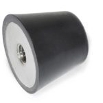
Part of some helical isolator designs is a patented crimp pattern. An array of mounting options and sizes exist with versions to meet commercial, industrial, and defense including MIL standards. The samples reviewed in the above video include both traditional bar and compact isolators — these square ones. One benefit to the compact versions is that they install with just a single point of attachment at each interface.
Wire-rope isolators cost effective in long run + protect machine frames @ITT_Enidine @WTWH_Tom Click To TweetOptions are through-hole, countersunk, and threaded bars for mounting. Its wire-rope isolators come in two-loop versions all the way to full loop numbers. Another option for high-fatigue applications is a “bellmouth” having mount bars with radii manufactured into the wire-rope hole edges. However, note that wire-rope isolators exhibit non-linear stiffness so small deflections (usually associated with vibration isolation) induce different spring rates than large shock deflections. Published values average vibration stiffness and shock-stiffness values for use in equations to predict system performance. Just remember that stiffness values are for full-loop versions — and reduced-loop versions have stiffnesses that are the unit’s standard stiffness times the ratio of actual loops to the standard number of full loops.
Wire-rope isolator selection is a three-step process. First the designer defines the system into which the isolator is going — by supported load, number of isolators to support the load, and whether the application will see just compression or rolling. Then the engineer defines the excitation and natural system frequencies and calculates maximum isolator stiffness.
The final step (before contacting the manufacturer) is to ensure the isolator will protect against shock loads. Values here depend on allowable transmitted acceleration, maximum isolator stiffness, response deflection, and allowable deflection.


Leave a Reply
You must be logged in to post a comment.