Edited by Terry Persun || Use of light detection and ranging (LiDAR) in the automotive industry is growing exponentially. The two most common variations are solid-state LiDAR and hybrid spinning LiDAR.
Solid-state LiDAR are non-spinning systems. Some employ a phased array to steer the laser beam sans moving parts; others include a tiny mirror to steer the laser beam. Still another solid-state design called flash LiDAR illuminates entire scenes in a single flash to allow detection of returned light via a two-dimensional array of sensors — similar to the operation of a digital camera. With few moving parts, these methods provide cost-effective LiDAR functionality.

Sometimes manufacturers put all the LiDAR electronics on a single chip, including the laser, any beam-steering circuitry, detectors for the return signal, and supporting computer power. But single-chip solutions for solid-state LiDAR are vulnerable to environmental challenges such as heat, cold, humidity, rain, and corrosive substances. End users needing to repair systems often find replacement ICs costly. What’s more, manufacturers are increasingly looking to offer lower-cost modular options that allow individual component swap-outs.
The latter is significant because a typical solid-state LiDAR setup provides a single fixed-in-place field of view of 120° or less. That means it takes at least four units to cover a full 360° safety zone. That contrasts with spinning LiDAR systems, which cover 360° operation with no blind spots due to gaps or overlapping … problems inherent to solid-state systems.
In addition, safety rules dictate that LiDAR must not generate laser output capable of damaging a person’s eyesight — even if that person were to look directly at the LiDAR unit for a number of seconds.
Reasons for solid-state hybrid LiDAR
Leveraging the advantages of both solid-state and spinning LiDAR is hybrid LiDAR. These designs have a field of view that is seamless and repeatable. Plus safety regulations permit moving laser sources to emit higher-power beams than stationary ones. So more powerful lasers let hybrid spinning LiDAR units map wide ranges and (when incorporated into systems for autonomous operation) help vehicles avoid the need to make short stops — and avoid the increased risk of body trauma to passengers. So even while solid-state LiDAR becomes increasingly common, demanding applications (including self-driving cars) will employ robust hybrids with superior long-range operation, higher resolution, and broader fields of view than other systems.
As we’ll see, trimming the cost and footprint of these LiDAR designs sometimes means using alternatives to the usual brushless dc (BLDC) motors employed for their spinning action.
Motors parts that LiDAR systems don’t need
Recall that brushless dc motors are more powerful than brushed motors — and avoid the friction and voltage drop associated with brushes for commutation. That’s why brushless dc motors are used in LiDAR systems. Spinning LiDAR designs usually turn at 200 to 500 rpm. The mirror assembly the motor turns is very light, so torque isn’t typically an issue. But many of today’s LiDAR systems use off-the-shelf (OtS) NEMA 17 and NEMA 23 motors — which can make for unnecessarily bulky builds.
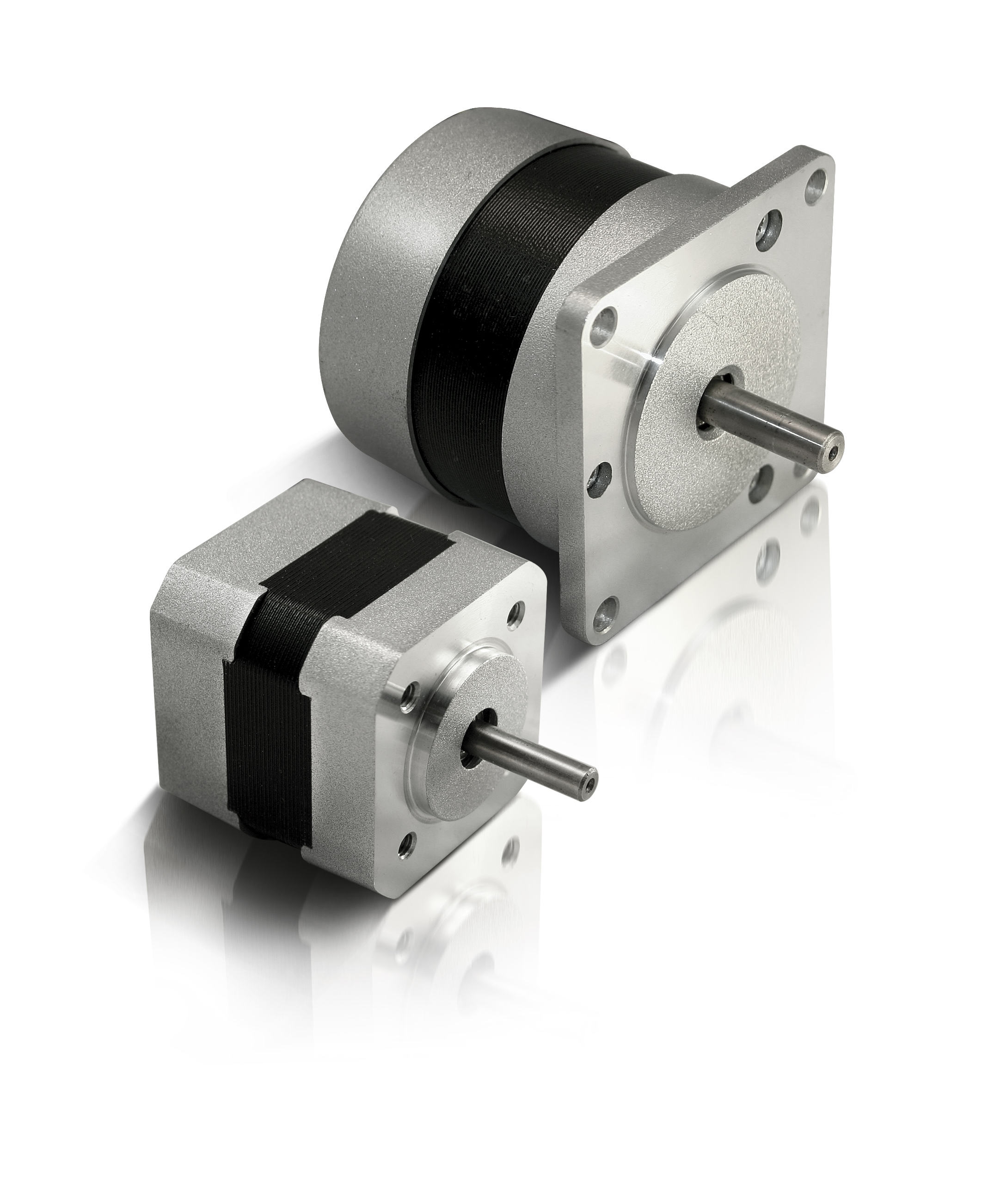
That’s because most OtS brushless dc motors are structurally and mechanically self-supporting. Endcaps suspend the rotor inside the stator; then the LiDAR’s moving assembly couples to an output shaft. In fact, motor ends can easily account for up to 50% of a motor’s overall length.
In contrast, frameless motors omit additional mounting supports, plates, brackets, and couplings to let design engineers directly integrate loads into the rotor design; in addition, the stator can be seamlessly incorporated into the system for a smaller design that doesn’t sacrifice performance.
Sleeker automobiles with compact LiDAR motors
Aerodynamics and visual styling are paramount in automotive design. It’s easier for engineers to incorporate wider flatter shapes to car exteriors than tall narrow shapes. Frameless motors can deliver this kind of geometry — with large diameters and less height than comparable OtS brushless dc motors. In addition, a portion of the LiDAR mirror load can sink down into the frameless design’s stator. Both of these options help reduce the overall LiDAR height for a streamlined shape.
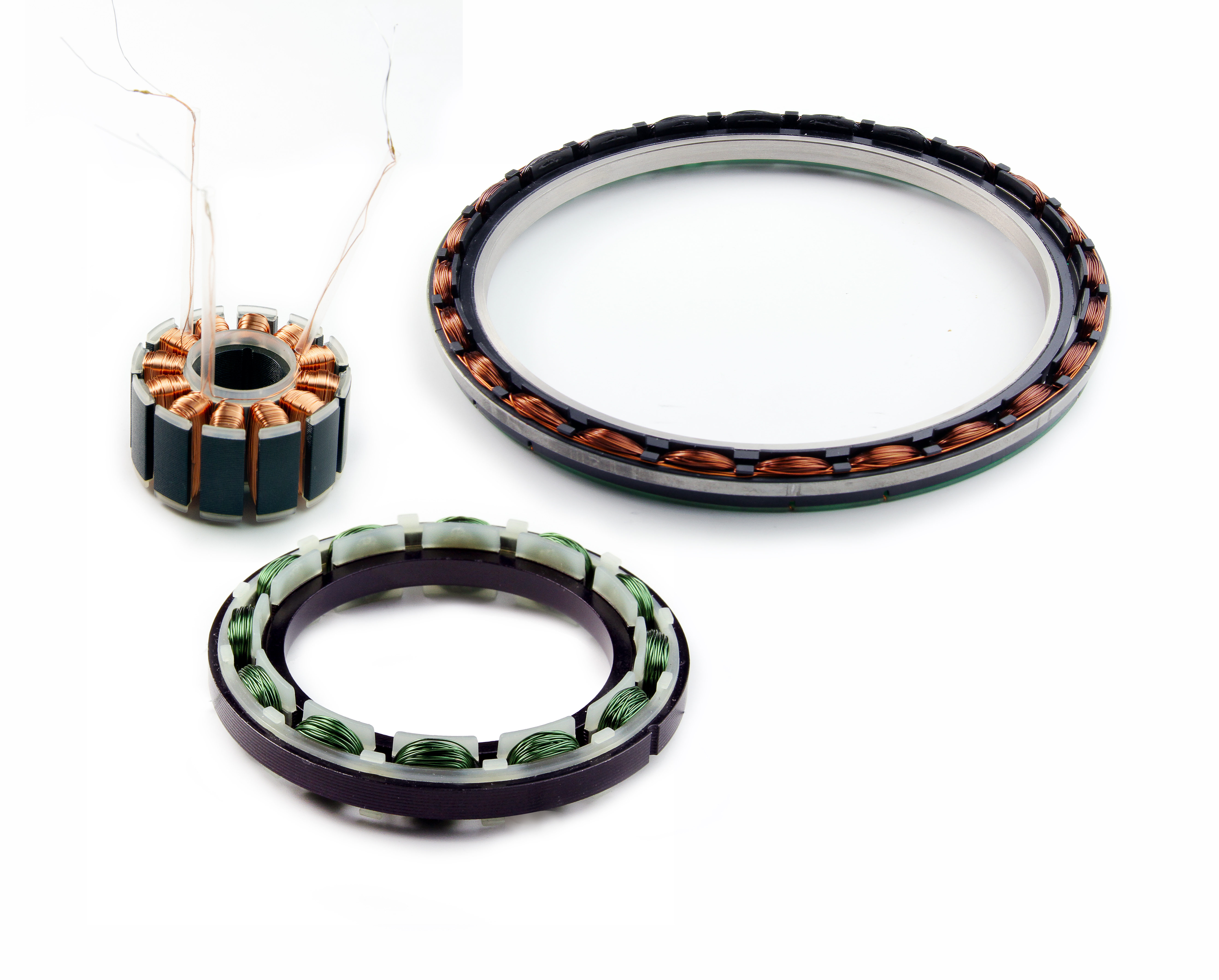
Frameless motors aren’t constrained to standard sized motors, so give design engineers more freedom to tailor motor shape and size to the application. This makes for LiDAR systems with the smallest footprint possible. When paired with the lightweight sensors of solid-state technologies, the motors have less mass to move and lower torque requirements to satisfy — allowing for a much smaller motor to do the job.
Off-the-shelf motors may be oversized for LiDAR systems. In contrast, custom motors are often more compact and (if supplied in high volumes) save thousands of dollars in manufacturing and production over the long run. For more information, visit Lin Engineering at linengineering.com.


Leave a Reply
You must be logged in to post a comment.