Iron core linear motors are known for their high continuous and peak force capabilities, good thermal management, and excellent force-to-size ratio. But they’re also known to produce cogging forces, which lead to force ripple, or variation in output force. But how much of a problem is cogging for iron core linear motors, and what are manufacturers doing to address it?
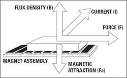
Image credit: Rockwell Automation
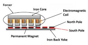
Cogging force is a result of the magnetic attraction between the “teeth,” or protrusions, of the iron lamination stack (the primary part, or forcer) and the permanent magnets of the magnet track (the secondary part). The product of the magnetic flux density and the current in the coils produces a horizontal force that propels the primary along the track.
But as the primary moves across the secondary, the individual teeth of the primary experience a fluctuating level of magnetic attraction to the magnets, meaning that the horizontal force also fluctuates. So at some positions, very little force is required to move the primary, and at other positions, more force is needed to overcome the magnetic attraction between primary and secondary. This fluctuation in the amount of force required to keep the primary moving at constant velocity is referred to as cogging force.
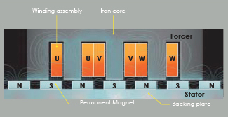
Image credit: Chieftek Precision
For point-to-point applications, some amount of cogging force, or force ripple, can be tolerated, since the application’s main concern is reaching the target position, and smoothness of motion isn’t critical. But for applications such as scanning and metrology, where smoothness of motion is paramount, cogging must be kept to a minimum.
Although the only way to eliminate cogging is to eliminate the attractive forces between the primary and the secondary — which is exactly what an ironless linear motor does, by embedding the windings of the primary in epoxy — manufacturers have developed solutions to significantly reduce cogging forces in iron core linear motors, making them suitable even for applications that are highly sensitive to force ripple.

Image credit: Aerotech
The first method to reduce cogging in an iron core linear motor is to alter the sharp transitions in attractive forces as the primary (lamination stack) moves over the secondary (magnet track). This done by skewing the positions of the magnets or of the laminations (although skewing the magnets is more common), or by using magnets with a special shape, such as an elongated octagon.
Both methods create an overlap of the magnetic fields of adjacent magnets. So rather than sharp transitions between the magnets (and, therefore, the magnetic attraction), there is a more gradual change in the magnetic attraction as the primary moves across the magnet track. While magnet skewing and shaping are the most common methods for reducing cogging forces, they also reduce the motor’s torque-producing capability and efficiency, since the alignment of the magnetic fields in these designs is not optimal.
Another approach uses destructive interference to cancel out the cogging forces. In this method, the primary contains more lamination teeth than there are magnets on the secondary (magnet track) – a winding method known as fractional winding. This imbalance between the number of teeth in the primary and magnets on the secondary allows the cogging forces caused by the inner teeth to cancel out.
The cogging force created by the outer teeth is addressed by adding a triangle to each end of the lamination stack, changing its shape from a rectangle to a parallelogram. These triangles on the ends of the lamination stack are shifted by 180 degrees in the magnetic cycle and create cogging forces equal but opposite to those created by the the outer teeth of the lamination stack. This, in combination with the fractional winding, virtually eliminates force ripple.

Image credit: Parker Hannifin
In addition to hardware solutions, which involve added cost and manufacturing complexity, cogging can also be addressed in the servo control system. Specifically, a feed-forward signal to the current command will smooth the motor’s force production and torque ripple. And keep in mind that torque ripple also causes velocity ripple, so a high-bandwidth velocity control loop, together with feed-forward commands, can help to smooth velocity for applications that are highly sensitive to speed fluctuations.
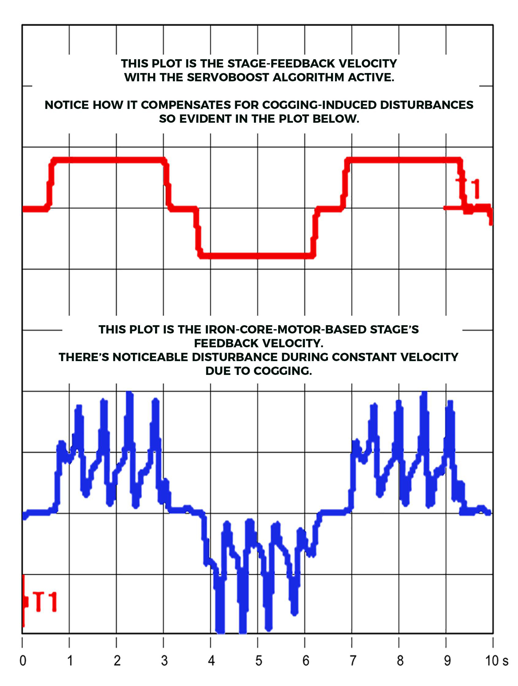
Image credit: ACS Motion Control
Feature image credit: Nippon Pulse


Leave a Reply
You must be logged in to post a comment.