
Servo systems are used when the application calls for precise control of position, velocity, or torque — or a combination of the three. Depending on the parameter being controlled, the servo system can be operated in torque mode, velocity mode, or position mode. Each mode requires control loops that allow the servo drive and controller to monitor the influencing parameters and provide the right commands to the motor to achieve the desired performance.
Servo control – Torque mode
In torque mode (also referred to as current mode), the current loop controls the motor’s behavior. Since torque is directly proportional to current, the servo controller obtains the actual motor current from the servo drive and uses this to determine actual motor torque. It then compares the actual torque value with the desired torque and adjusts the current delivered to the motor to achieve the desired torque. The current control loop is typically tuned with a PI (proportional-integral) controller, and current loop parameters are often set by the manufacturer.
Applications that require torque mode control range from winding, where constant tension must be held on a web of material while it’s wound, to injection molding, where constant clamping force must be applied to the mold.
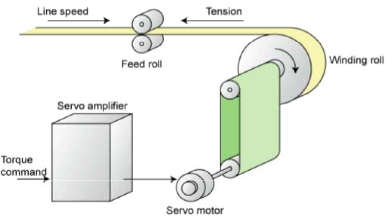
Image credit: Mitsubishi Electric
The amount of torque a motor produces depends on the amount of current it receives. And torque determines the motor’s acceleration, which affects velocity and position. Thus, servo systems always include a current control loop.
Servo control – Velocity mode
When an application requires that the motor maintains a set speed, even under varying loads, velocity mode is used. In velocity mode, the motor speed is controlled by the amount of voltage sent to the motor. But to change the motor’s velocity (to accelerate or decelerate) requires an increase or decrease in motor torque, so a current control loop is also required in velocity mode.
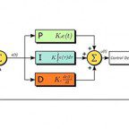
When more than one control loop is used, the loops are cascaded, with current control being the innermost loop and the velocity control loop added “around” the current loop. When a position control loop is used, it is added around the velocity loop, forming the outermost loop. Tuning is done from the inner to the outer loop, so the current loop is tuned first, then the velocity control loop, then the position control loop.
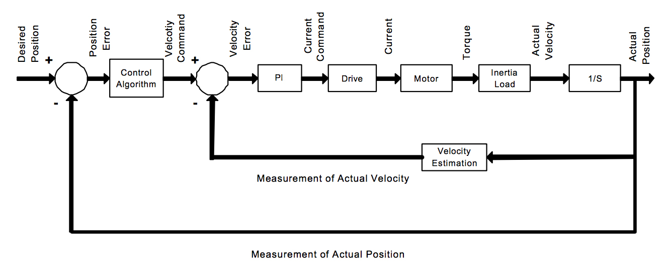
Image credit: Integrated Industrial Technologies, Inc.
Many advanced servo controllers can switch between control modes “on the fly” — transitioning from velocity mode to torque mode, for example, while the system is in operation without creating instabilities or interruptions.
The velocity control loop obtains speed information from an encoder or resolver to determine the error between actual and commanded velocity and uses this error to determine what current (torque) is required for the motor to correct the speed error. The velocity control loop is typically a PI controller, and servo systems operating in velocity mode sometimes include parameters that smooth acceleration and deceleration to minimize the effects of jerk.
Examples of applications that use velocity mode are conveyor tracking, dispensing, and machining processes such as grinding or polishing, where motor load varies but velocity needs to be maintained throughout the process.
When the application calls for all three control loops
Servo systems can also be operated in position mode, allowing the motor to move the load to a precise location, either relative to a starting location or based on an absolute position. To achieve position mode in servo control, all three control loops are typically required: torque, velocity, and position. This is because the motor’s speed must be monitored to determine its position, and torque must be monitored to determine the how much current the motor needs in order to reach the commanded position, without undershoot or overshoot. The position control loop uses a PI or a PID (proportional-integral-derivative) controller.

Leave a Reply
You must be logged in to post a comment.