
Design engineers who employ advanced damping and vibration isolation can vastly improve the performance of their industrial-automation machinery.
By Larry Cavalloro • ACE Controls
A top objective for designers of industrial-automation machinery is to build and tune axes for minimal vibration (free or forced); gently and precisely slow axes’ moving masses; and render unavoidable machinery vibration either isolated or damped — in other words, fully dissipated. These techniques let machine axes settle back to equilibrium as quickly as possible — which is especially useful for those running high-speed reciprocating, positioning, or other precise automation tasks.
The vast host of options for damping and vibration isolation include industrial and safety shock absorbers, profile dampers, rotary dampers, industrial gas springs, hydraulic dampers, vibration isolators, air springs and hydraulic feed controls. We put the technologies into four broad categories.
Automation control with shock absorbers and dampers include miniature shock absorbers, industrial shock absorbers, heavy industrial shock absorbers, profile dampers, and damping pads.
Options for motion control include push-type and pull-type industrial gas springs, hydraulic dampers, hydraulic feed controls, door dampers, and rotary dampers.
Variations classified as vibration control include rubber-metal isolators, vibration-isolating pads, and low-frequency pneumatic leveling mounts.
Safety products include safety shock absorbers, safety dampers, and clamping elements.
In this feature, we focus on one leading option from the first category — that of automation control with industrial shock absorbers. We’ll consider the options for miniature shock absorbers, industrial shock absorbers, heavy-duty shock absorbers, and dampers in upcoming installments.
Industrial shock and damping options compared
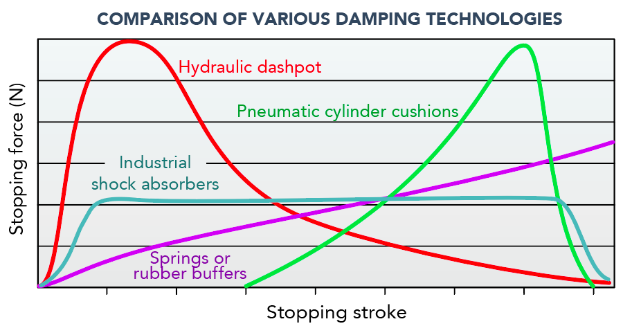
Hydraulic dashpots deliver a high stopping force at the stroke start. With only one metering orifice, moving loads under the control of a hydraulic dashpot sees abrupt slowdown at the start of the stroke. Braking force rises to a high peak at the start of the stroke (giving high shock loads) and then falls away rapidly.
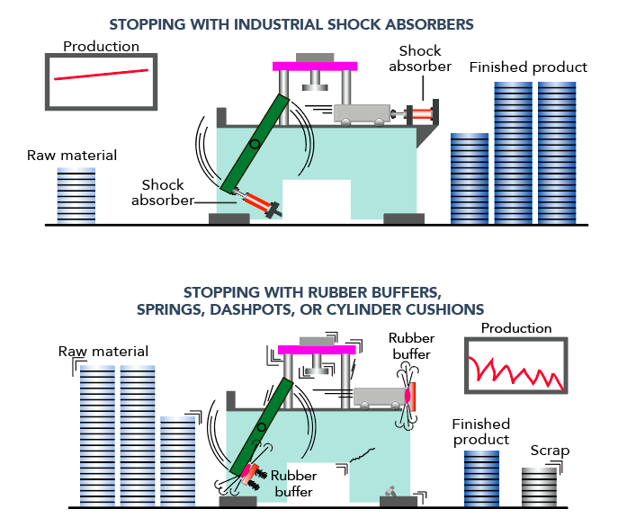
Springs and rubber buffers exhibit high stopping forces at end of stroke. At full compression, they also store energy rather than dissipating it … causing loads to rebound.
Air buffers and pneumatic cylinder cushions output high stopping force at end of stroke. Due to the compressibility of air, these exhibit sharply rising force towards the stroke end … so most of the energy is absorbed near the end of the stroke.
Industrial shock absorbers deliver uniform stopping force through the entire stroke. The moving load is smoothly and gently brought to rest by a constant resisting force throughout the entire shock absorber stroke. The load is decelerated with the lowest possible force in the shortest possible time — which in turn eliminates damaging force peaks and shock damage to machines and equipment. When plotted, the deceleration force-stroke curve is linear. Such smooth and gentle shock absorbing also serves to reduce noise generated by automated machinery.
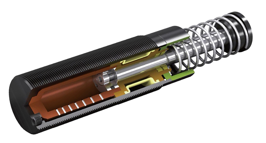
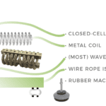
How industrial shock absorbers work
It’s clear that automated applications requiring the slowing of moving masses with constant damping force through the stroke benefit from the use of industrial shock absorbers. But how do they operate? In short, industrial shock absorbers work by converting kinetic energy into heat for controlled deceleration. In short, a piston acts as the interface between external moving masses requiring deceleration and the shock’s internal system of components. When an external mass impacts the piston, the latter retracts into the shock body. That in turn pressurizes hydraulic fluid such as automatic transmission fluid (ATF) inside … and forces this fluid to flow through a pressure chamber with metering orifices. The labyrinth of orifices serves to progressively restrict the fluid — causing it to rise in temperature. This heat is then expended to the shock outer body and outward to the surrounding environment.
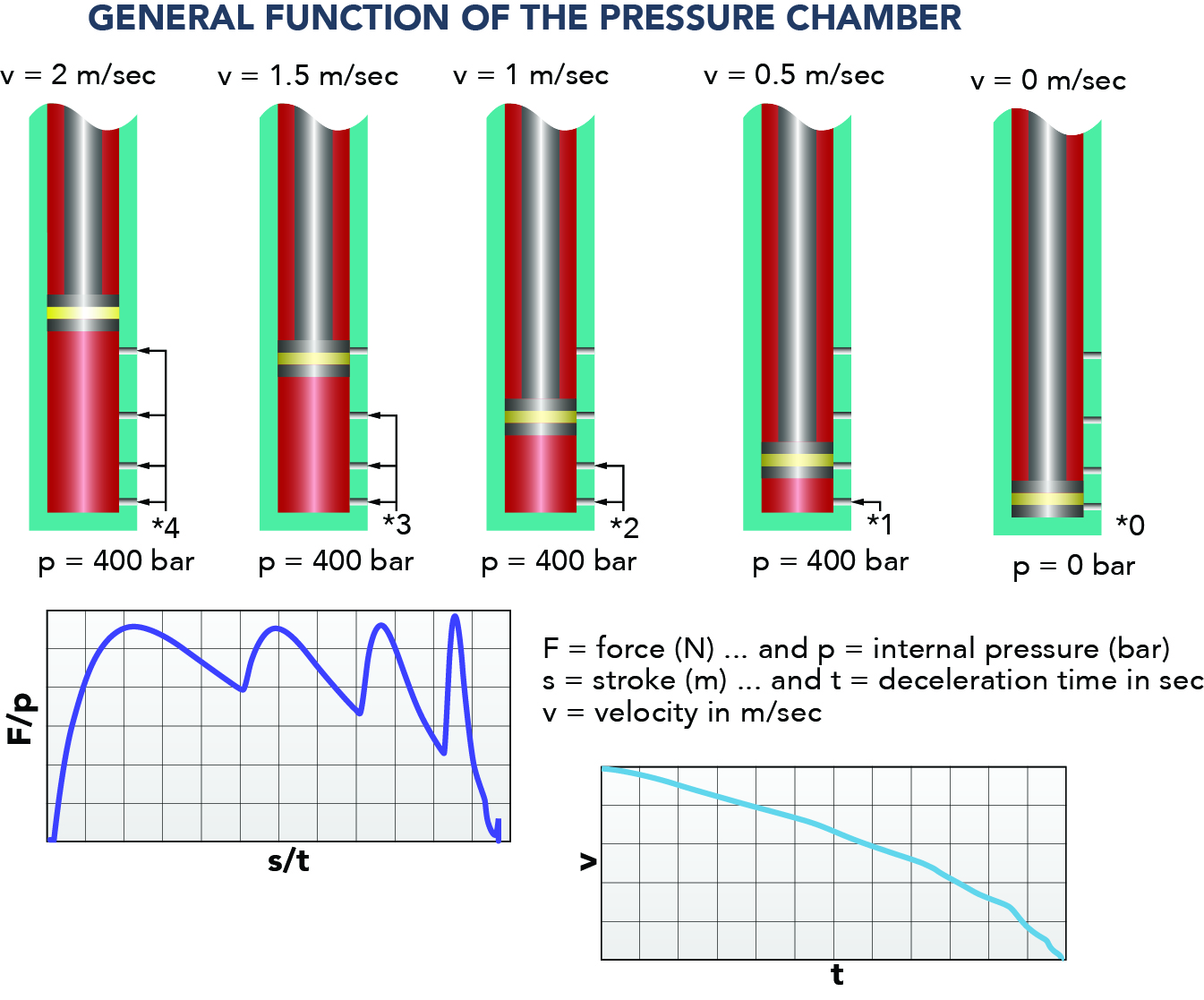
In industrial shock absorbers with some measure of adjustability, a secondary pressure chamber with its own labyrinth of orifices fits around the primary pressure chamber — to create channels of variable restriction.
Upon release of the mass from the piston, usually a return spring resets the piston to its extended position. In some cases, the return spring is internal to the shock absorber … and in other cases, it’s externally located around the piston shaft.
How to size industrial shock absorbers
Let’s walk through an example of how a design engineer might select a shock absorber for an automated machine axis. Consider a mass horizontally driven from one side and riding on a frictionless surface such as a passive-roller conveyor:
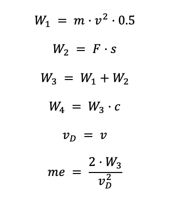
Where W1 = Kinetic energy per cycle, Nm
m = Mass to be decelerated and me = Effective weight, both in kg
v = Velocity at impact and vD = Impact velocity at shock absorber, both in m/sec
s = Shock-absorber stroke, m
W2 = Propelling force energy per cycle and W3 = Total energy per cycle, both in Nm
W4 = Total energy per hour, Nm/hr — listed in capacity charts for room temperature (and reduced values at higher temperature ranges)
n = Number of shock absorbers (in parallel)
Note that final impact velocity can be 1.5 to twice that of average velocity — something for which engineers must account when calculating kinetic energy.
Now assume we have m = 36 kg and v = 1.5 m/sec
F = 400 N and c = 1,000/hr with s = 0.025 m (chosen)
That means we have W1 = 36 · 1.52 · 0.5 = 41 Nm
W2 = 400 · 0.025 = 10 Nm
W3 = 41 + 10 = 51 Nm
W4 = 51 · 1,000 = 51,000 Nm/hr
me = (2 · 51) / 1.52 = 100 kg
At this point, the engineer can choose a shock-absorber model based on manufacturer charts.
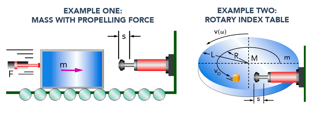
Consider another example — that of a rotary index table with propelling torque.
Where ω = Angular velocity at impact, rad/sec
M = Propelling torque, Nm
R= Radius at which the shock absorber engages item of table, m
L = ½ the indexing table total radius, m
If we assume m = 1,000 kg and v = 1.1 m/sec with M = 1,000 Nm and choose s = 0.050 m — with L = 1.25 m, R = 0.8 m, and c = 100 /hr we get:
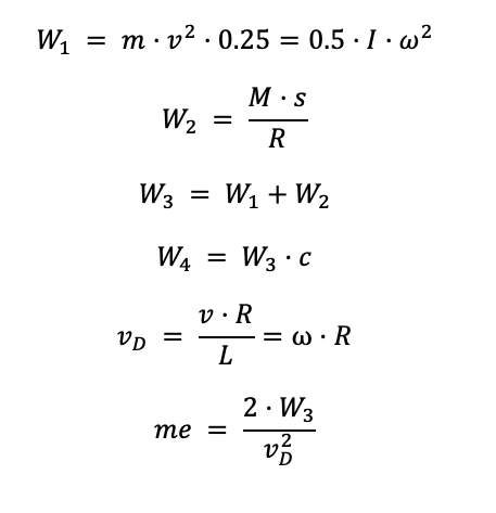
W1 = 1,000 · 1.12 · 0.25 = 303 Nm
W2 = (300 · 0.025) / 0.8 = 63 Nm
W3 = 303 + 63 = 366 Nm
W4 = 366 · 100 = 36,600 Nm/hr
vD = (1.1 · 0.8) / 1.25 = 0.7 m/sec
me = (2 · 366) / 0.72 = 1,494 kg
At this point, the engineer can choose a shock-absorber model based on manufacturer charts — accounting for side load angle (tan α = s/R) and shock-absorber capacity to handle such loading to ensure long and reliable operation. Where the assembly requires additional support due to side-load impact angles exceeding 3° (even to 25°) the addition of a side-load adaptor can protect the shock absorber’s rod bearings from increased wear that would otherwise reduce useful component life.
Now consider a real-world iteration of an automated rotary-indexing table with propelling torque — that of a large telescope’s optical system. Here, industrial shock absorbers boost the safety of swivel and braking functions. The moveable 15,000 kg telescope can sweep through two DOFs with a motor-driven turntable and twin wheel discs that ride on bearings for ±90° rotation from horizon to horizon. Industrial shock absorbers protect the telescope’s delicate subcomponents from shock from overshooting swivel limits … so if the telescope inadvertently overshoots its permissible swivel range, the shock absorbers safely damp the travel.
In much the same way, industrial shock absorbers improve the positioning accuracy of a machine-loading design by serving as precision limit stops. Rodless pneumatic cylinders and twin gripper slides move independently at 2 to 2.5 m/sec. The shock absorbers work as brakes to stop a 25-kg mass up to 540 times per hour. The specific model employed for this task allows quick end-position adjustments … with higher travel speeds and shorter cycle sequences than comparable brake systems as well.
ACE Controls | www.acecontrols.com


Leave a Reply
You must be logged in to post a comment.