
Dynamic brakes in electric motor drives divert rising DC bus voltage seen during load deceleration. Here we explain how to size the resistors that process that voltage.
By Lawrence Kren | Contributing writer
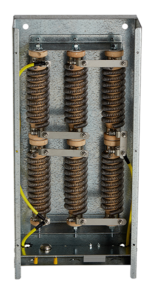
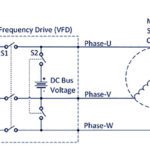
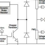
Dynamic brakes divert rising DC bus voltage to an appropriately sized resistor where that voltage is then dissipated as heat. This process is triggered when a brake transistor in the drive switches on — when DC bus voltage exceeds nominal by a set amount.
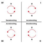
Sizing a brake resistor requires knowledge of the drive and motor specs (power, voltage, rpm, and inertia) which can be found in manufacturer data sheets. So too does resistor sizing rely on quantifying process variables — including load inertia, frictional torque, deceleration time, and duty cycle. In general, equipment with high frictional torque such as fans and pumps don’t need dynamic brakes. In contrast, applications characterized by high inertia and low frictional torque can benefit from them.

Electric power dissipates in a braking resistor according to:
PPB = V2/R
Where PPB = Peak braking power (Watts)
V = Bus voltage at which the brake transistor turns on (vdc)
R = Resistance (ohms)
R is the maximum allowable resistance value; exceeding this value can trigger a DC bus over voltage. Drive manufacturers also specify minimum values of brake resistance keyed to a drive’s bus voltage and power rating.
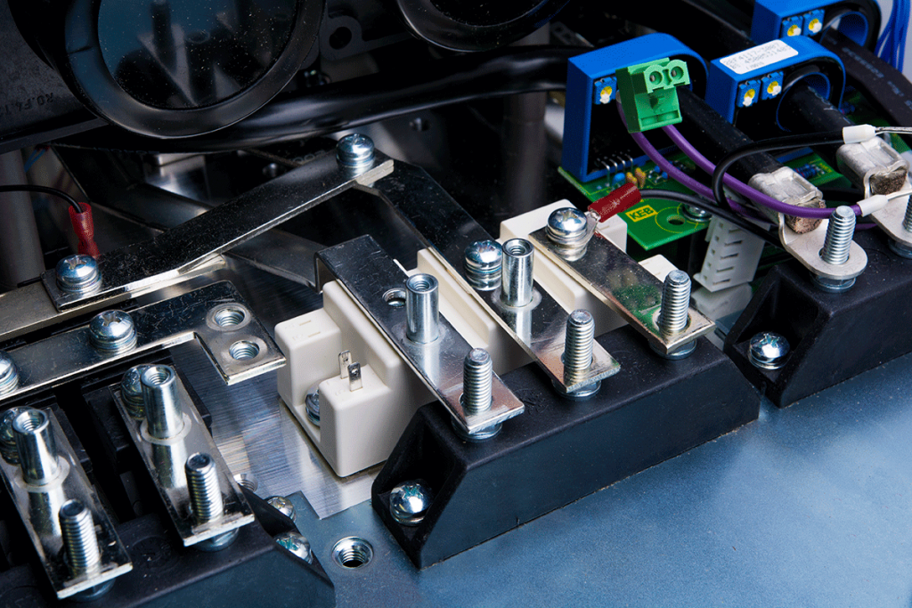
How fast and frequently a dynamic brake slows a load determines brake resistor wattage. Applications with overhauling or continuous loads (such as dynamometers) employ resistors with a wattage rating directly proportional to applied torque. In contrast, a brake resistor used in an emergency e-stop momentarily sees peak power as a load slows to halt and may therefore have a smaller-than-peak wattage rating. Resistors (depending on type) can handle many times their rated power for durations on the order of several seconds. Resistor manufacturers quantify this energy rating in Watt-sec. For emergency e-stops and other braking events that don’t happen frequently (so representing a low-percent duty cycle) the task is to match rotational kinetic energy to a resistor capable of dissipating it in a prescribed time.
To do this, first calculate system total inertia:
JT = JM + JL x n2
JT = Total reflected inertia at the motor shaft (kg-m2)
JM = Motor inertia (kg-m2)
JL = Load inertia (kg-m2)
n = Gear ratio = load speed/motor speed (dimensionless); n = 1.0 for directly coupled loads
Next, calculate the rotational energy stored in the system:
E = ½JT x ω
E = Rotational energy (Joules)
ω = Angular velocity (rad/sec) = 2π x rpm / 60

The amount of time needed to decelerate a rotating load is:
Δt = JT x Δω / (τM + τF)
Δt = Time (sec)
Δω = Change in angular velocity (rad/sec)
τM = Motor braking torque (N-m)
τF = Frictional torque (N-m)
A conservative approach neglects frictional torque, then all arresting torque is supplied by the motor through the brake resistor. Assume, for example, a brake resistor is sized to provide brake torque equal to motor rated torque.
PPB = P
P = ω x τ
P = Motor rated power (Watts)
ω = Angular velocity (rad/sec) = 2π x rpm / 60
τ = Motor rated torque (N-m)
The question may be how much inertia can be added to the system and bring it to halt while remaining within the brake resistor’s energy rating.
A resistor’s energy rating indicates how long in seconds it can absorb a certain amount of power without damage. To check, calculate the rotational energy of the total reflected inertia at the motor shaft and compare it with the resistor energy rating. If rotational energy is less the resistor energy rating, the resistor can handle the specified braking load. If the total reflected inertia energy exceeds the resistor energy rating, either select a higher capacity resistor or reduce the brake torque.
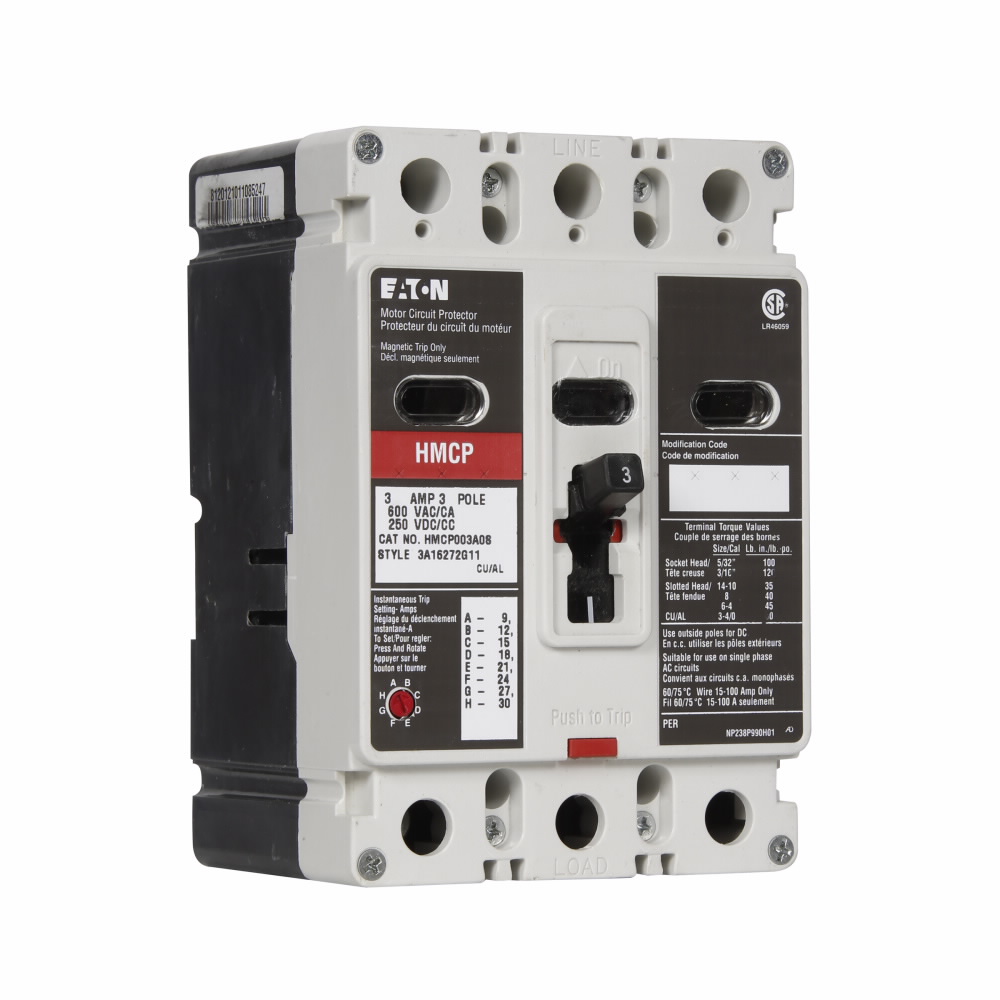
Be sure to consider brake resistor ohmic heating in high duty cycle applications. Overuse of a braking resistor can thermally damage it. A separate motor circuit protector attached to the drive is often used to limit current level and duration to a brake resistor.
Motion Control Tips | motioncontroltips.com
Leave a Reply
You must be logged in to post a comment.