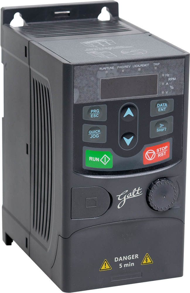
Image credit: Galt Electric
AC induction motors excel at driving high-inertia loads at high speeds — in fans, saws, conveyors, and mills, for example — and variable frequency drives make it possible to match the motor speed to the application requirements by varying the frequency of the supplied voltage.
But when quick stops are needed — whether for safety reasons or to prevent wasted time and lost productivity waiting for the load to come to a standstill — high speeds and high load inertia make it difficult to brake the motor and stop the load.
In an AC induction motor, three-phase AC power is fed to the stator windings, creating a magnetic field that rotates. This magnetic field induces a current and a corresponding magnetic field in the rotor. The interacting magnetic fields of the rotor and stator cause the motor to turn.
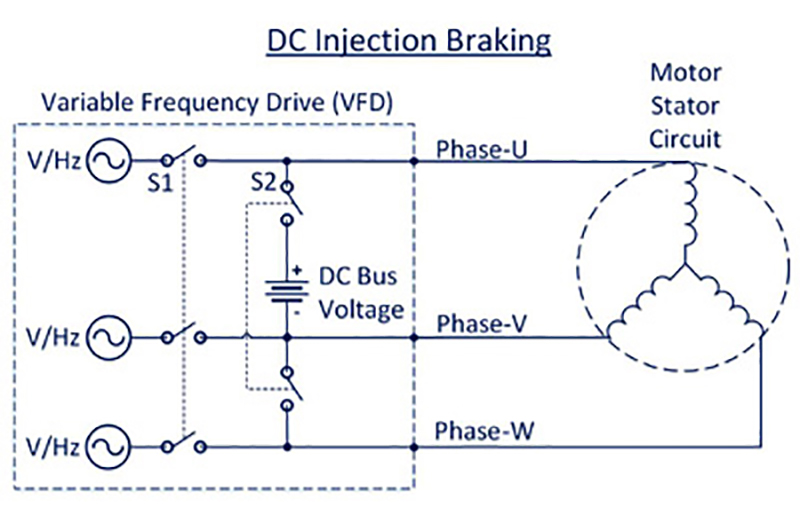
DC injection braking works just as its name implies — by injecting DC voltage into the motor windings. Before DC injection braking can begin, the AC power to the motor stator must be disconnected — typically by the opening of a relay. In turn, a relay controlling motor braking closes, allowing DC voltage — sourced by the DC bus — to be applied to the windings. To prevent the braking current from exceeding the drive and motor ratings, circuitry in the VFD or in an external braking module controls the amount of voltage applied.

Image credit: KB Electronics, Inc.
When DC current is applied to the motor windings, it creates a fixed (rather than rotating) magnetic field. Braking action is produced by the rotor working to align to this stationary field. The higher the DC current, the stronger the braking force.
The energy generated during braking is dissipated as heat by the motor (particularly the rotor) and the controller, so thermal limitations of these components dictate how much braking current can be applied and the amount of time for which it can be applied before overheating occurs. If DC injection braking is used frequently, the additional heating created during braking must be taken into account when sizing the motor.
Although DC injection braking can be used to hold a load stationary, it’s not generally recommended due to heat generated in the motor. And because DC injection brakes require a constant power supply, they’re not considered fail-safe devices.
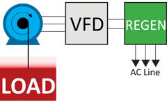
DC injection braking is just one of several electrical methods of bringing an AC induction motor to a stop. Two other forms of braking — dynamic braking and regenerative braking — convert mechanical energy generated as the rotor slows down into electrical energy.

Image credit: Bonitron
In a dynamic braking system, this electrical energy is released as heat through a voltage regulated resistor. In regenerative braking, this electrical energy is fed back to the power supply or to a common DC bus. Dynamic braking is best for applications that require only periodic braking without high heat dissipation demands, while regenerative braking is best for applications with frequent stops and starts or overhauling loads.
A drawback of both dynamic braking and regenerative braking is that the braking force decreases as the motor (rotor) slows down. DC injection brakes are often used in conjunction with dynamic or regenerative braking systems to provide the final braking power required to fully stop the motor and load. And because DC injection brakes can cause thermal problems for the motor and drive, the use of dynamic or regenerative braking in the beginning, together with DC injection braking at the end of the stop, reduces the risk of overheating while providing fast, complete stopping for high-inertia, high-speed AC induction motor applications.


Leave a Reply
You must be logged in to post a comment.