
Variable frequency drives use a technique referred to as pulse-width modulation (PWM) to provide voltage of varying frequency to an AC induction motor. The inverter, or output, stage of the VFD uses insulated gate bipolar transistors (IGBTs) that switch on-and-off rapidly, creating trapezoidal pulses of varying width to simulate AC sinusoidal voltage.
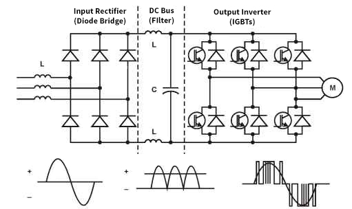
Image credit: what-when-how.com
But the windings in an AC motor don’t accept this power immediately. They take time to build up a magnetic field — and therefore, current — due to their inductance. And the rapid switching of the IGBTs causes a spike in voltage at the leading edge of each pulse. (The rate at which the voltage increases is known as the dV/dt, or rise time.) Once the power reaches the motor, another disparity occurs — the voltage encounters a higher impedance at the motor than that of the supply cable.
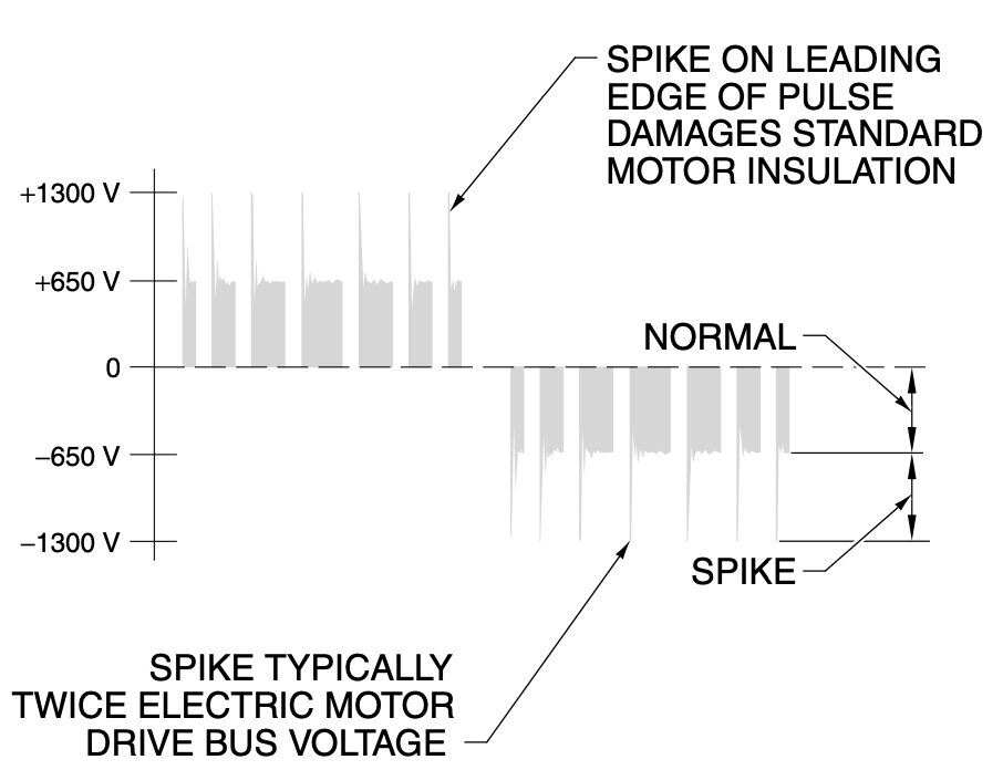
Image credit: A. Mazur and W. Weindorf
These factors — the voltage spikes caused by PWM, the time required for the motor’s windings to accept the power, and the difference in impedance between the cable and the motor — all work together to cause some of the voltage to be reflected from the motor, through the cable, and back to the drive. This phenomenon is known as a reflected wave.
If the time it takes for a voltage pulse to travel from the VFD to the motor is more than half of the pulse’s rise time, the reflected voltage pulse will combine with an incoming voltage pulse, increasing the amplitude of the pulse at the motor input to a level higher than the VFDs DC bus voltage. If the motor impedance is much greater than the cable impedance, the reflected pulse amplitude can equal that of the incoming pulse, creating a reflected wave that’s twice than the VFDs DC bus voltage.
Further, the inductance and capacitance (recall in AC circuits, inductance and capacitance are components of impedance) of each component — the drive, cable, and motor — can form a resonant circuit that causes the edges of the voltage pulses to take on an underdamped sinusoidal waveform. This is sometimes referred to as cable ringing, and it can cause voltage peaks that are much greater than twice DC bus voltage — enough to damage the motor and the cable.
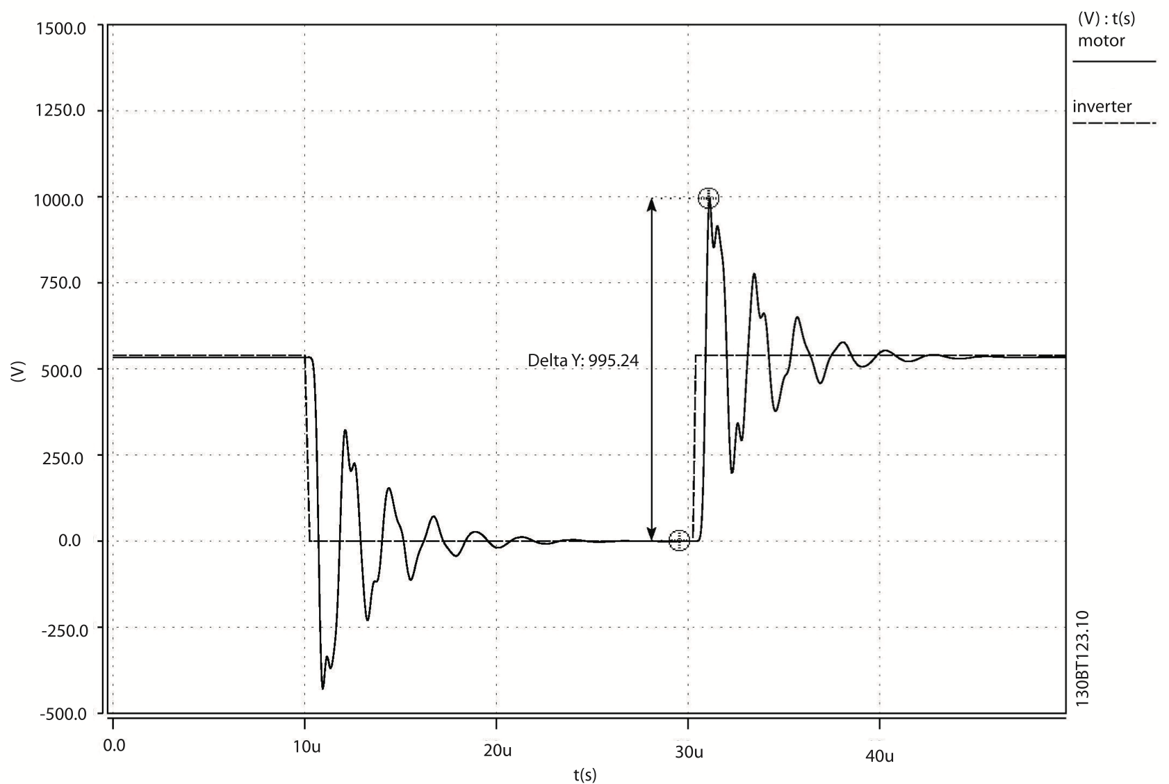
Image credit: Danfoss
Note that motor impedance increases as motor size decreases. Therefore, smaller motors have a higher impedance and are more susceptible than larger motors to cable ringing for a given cable length, due to a greater mismatch between motor and cable impedances.
One of the primary recommendations to prevent cable ringing is to use the shortest cable possible between the VFD and the motor. Longer cables have higher capacitance, which causes higher voltage spikes. Reducing the cable length also helps ensure that the time required for the pulse to travel from the VFD to the motor is less than half of the pulse’s rise time, reducing the amplitude of reflected waves.
The “critical length” of the cable depends on specific shape of the PWM output, the switching frequency of the IGBTs, the rise time of the pulse, and even the cable type, but general recommendations for critical length can be as short as 25 ft or up to several hundred feet, depending on the motor’s horsepower and peak voltage rating.
Lowering the switching frequency of the IGBTs in the inverter can also reduce the effect of reflected waves and cable ringing, because a lower frequency produces fewer voltage pulses per unit of time. However, a lower switching frequency reduces the ability to control the motor’s torque and creates more audible noise.
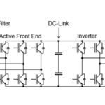
Another common recommendation is to install an output reactor (also referred to as a load reactor) to the output of the drive, or as close as possible. Output reactors increase the cable’s inductance (and, therefore, impedance) to reduce the impedance mismatch between the cable and the motor. Adding a dV/dt filter (also referred to as a dV/dt choke) can also decrease the rise time of the PWM pulses and reduce the peak voltages at the motor terminal.


Leave a Reply
You must be logged in to post a comment.