• Skip to primary navigation
  • Skip to main content
  • Skip to primary sidebar
  • Skip to footer
  • Advertise
  • Subscribe

Motion Control Tips

Automation • Motion Control • Power Transmission

  • News
    • Industry News
    • Editor Blogs
  • Controls
    • HMIs
    • PC-Based Controllers
    • PLCs + PACs
    • Stand-Alone Controllers
    • Software
  • Drives
    • Servo Drives
    • Stepper Drives
  • Encoders
    • Absolute Encoders
    • Incremental Encoders
    • Rotary Encoders
  • Mechanical
    • Bearings
    • Brakes + Clutches
    • Belt + chain
    • Couplings
    • Gears + Gearing
    • Lubrication
    • Shock + Vibration Mitigation
    • Springs + Rings + Seals
  • Linear
    • Actuators
    • Linear Motors
    • Linear Encoders
  • Motors
    • AC Motors
    • DC Motors
    • Brushless Motors
    • Gearmotors
    • Piezo Motors
    • Servo Motors
    • Stepper Motors
  • Systems
    • Conveyors + linear transport systems
    • Gantries + Stages
    • Rotary Tables
    • Grippers + End Effectors
    • Robotics
  • Networks
    • Connections + Sliprings
    • Fieldbuses
    • I/O
    • Sensors + Vision
  • Resources
    • FAQs
      • Motion Casebook
      • Motion Selection Guides
    • Suppliers
    • Video
You are here: Home / FAQs + basics / What’s the difference between resistance, reactance, and impedance?

What’s the difference between resistance, reactance, and impedance?

September 15, 2020 By Danielle Collins Leave a Comment

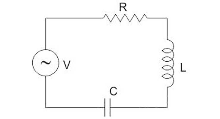
DC circuits are relatively easy to analyze, due to current flowing in one direction, with resistance being the main element of the circuit. AC circuits, on the other hand, are more complex, since voltage and current alternate direction with a given frequency. Whereas DC circuits have resistance, AC circuits often have resistance and another property, known as reactance. Impedance is the combination of resistance and reactance.

resistance reactance impedance


Components known as resistors prevent current from flowing — in other words, they have the property of resistance. Resistors are found in both AC and DC circuits, and the energy that is prevented from flowing is expelled as heat. Mathematically, resistance is simply voltage divided by current.

resistance reactance impedance

R = resistance (ohms)

V = voltage (volts)

I = current (amps)


Reactance is a property that opposes a change in current and is found in both inductors and capacitors. Because it only affects changing current, reactance is specific to AC power and depends on the frequency of the current. When reactance is present, it creates a 90 degree phase shift between voltage and current, with the direction of the shift depending on whether the component is an inductor or a capacitor.

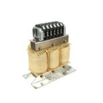
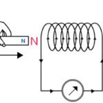
Reactance that occurs in an inductor is known as inductive reactance. When inductive reactance is present, energy is stored in the form of a changing magnetic field, and the current waveform lags the voltage waveform by 90 degrees. Inductive reactance is caused by devices in which wire is wound circularly — such as coils (including line reactors), chokes, and transformers.

resistance reactance impedance

XL = inductive reactance (ohms)

f = frequency (Hz)

L = inductance (henrys)

Reactance that occurs in a capacitor is known as capacitive reactance. Capacitive reactance stores energy in the form of a changing electrical field and causes current to lead voltage by 90 degrees. Capacitance is created when two conducting plates are placed parallel to one another with a small distance between them, filled with a dielectric material (insulator).

resistance reactance impedance

XC = capacitive reactance (ohms)

C = capacitance (farads)


Impedance is the combination of resistance and reactance (both inductive and capacitive) and is a complex number, containing both real and imaginary parts. (The real part of impedance is resistance, while the imaginary part is reactance.) Impedance has both magnitude and phase.

resistance reactance impedance

Z = magnitude of impedance (ohms) in a series circuit

XT = total reactance (ohms) = XL – XC

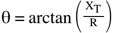
θ = phase of impedance (degrees)

You Might Also Like

Filed Under: FAQs + basics, Featured

Reader Interactions

Leave a Reply

You must be logged in to post a comment.

Primary Sidebar

LEARNING CENTER

Design World Learning Center

Motion Control Handbook

“mct
EXPAND YOUR KNOWLEDGE AND STAY CONNECTED
Get the latest info on technologies, tools and strategies for Design Engineering Professionals.

RSS Featured White Papers

  • Robotic Automation is Indispensable for the Logistics Industry’s Continued Growth and Success
  • Reliable Linear Motion For Packaging Machines
  • Polymers Outperform Metals In Precision Gearing

Footer

Motion Control Tips

DESIGN WORLD NETWORK

Design World Online
The Robot Report
Coupling Tips
Linear Motion Tips
Bearing Tips
Fastener Engineering.
Wire and Cable Tips

MOTION CONTROL TIPS

Subscribe to our newsletter
Advertise with us
Contact us
About us

Copyright © 2025 · WTWH Media LLC and its licensors. All rights reserved.
The material on this site may not be reproduced, distributed, transmitted, cached or otherwise used, except with the prior written permission of WTWH Media.

Privacy Policy | RSS