
There are two fundamental types of stepper drives: L/R drives and chopper drives.
L/R stepper drives are also referred to as “constant voltage” drives, because they supply constant voltage to the motor windings. The current produced in the windings depends on the motor’s time constant, which is the relationship between its inductance and resistance (L/R). The time constant causes current to increase slowly with each voltage pulse. So for very high pulse rates (i.e. high motor speeds), full current, and thus full rated torque, may not be reached. This limits the use of L/R drives to primarily low-speed applications.
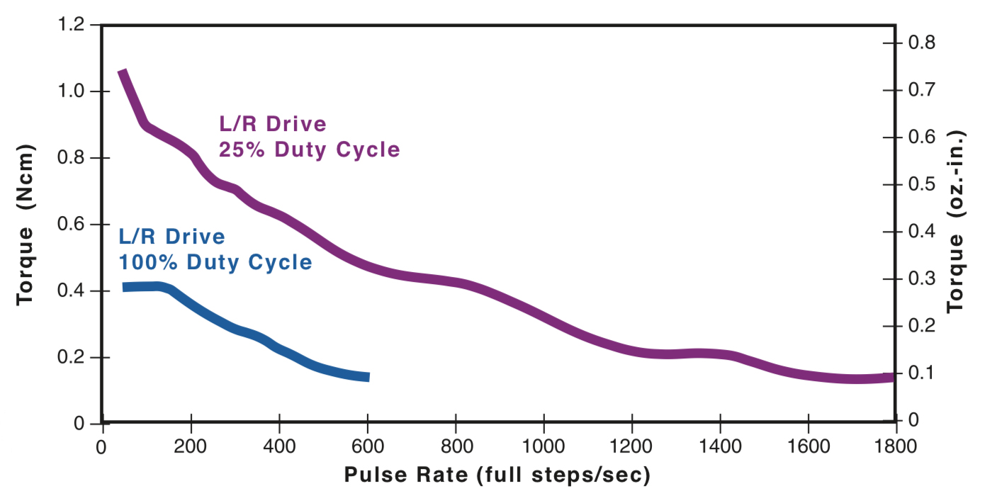
Image credit: AMETEK Inc.
Current in the windings can be increased by using higher supply voltage, but motor temperature rise then becomes a problem. When the applied voltage is high, the “off” time (when no power is applied) must be long enough to prevent the motor from overheating. Another option is to add resistors in series to improve the time constant (L/2R or L/4R, for example) and increase the voltage. But resistors waste power through heat generation, so efficiency is reduced.
Resistance (R) affects the maximum current in the windings, according to Ohm’s law, I = V/R.
Inductance (L) affects the rate of change of current in the windings, according to the relationship, dI/dt = V/L.
Because of the torque and speed limitations of L/R stepper drives, an increasing number of stepper motor applications now use chopper drives. These drives are also referred to as “constant current” drives because they supply constant current to the motor windings, by “chopping” the output voltage (i.e. turning the output voltage on-and-off very rapidly).
With each motor step, a very high voltage (typically eight times the motor’s nominal voltage) is supplied to the motor windings. This high voltage gives a very short current rise time, according to the relationship for an inductor (dI/dt = V/L), and it causes higher current to be produced, according to Ohm’s law (I = V/R).
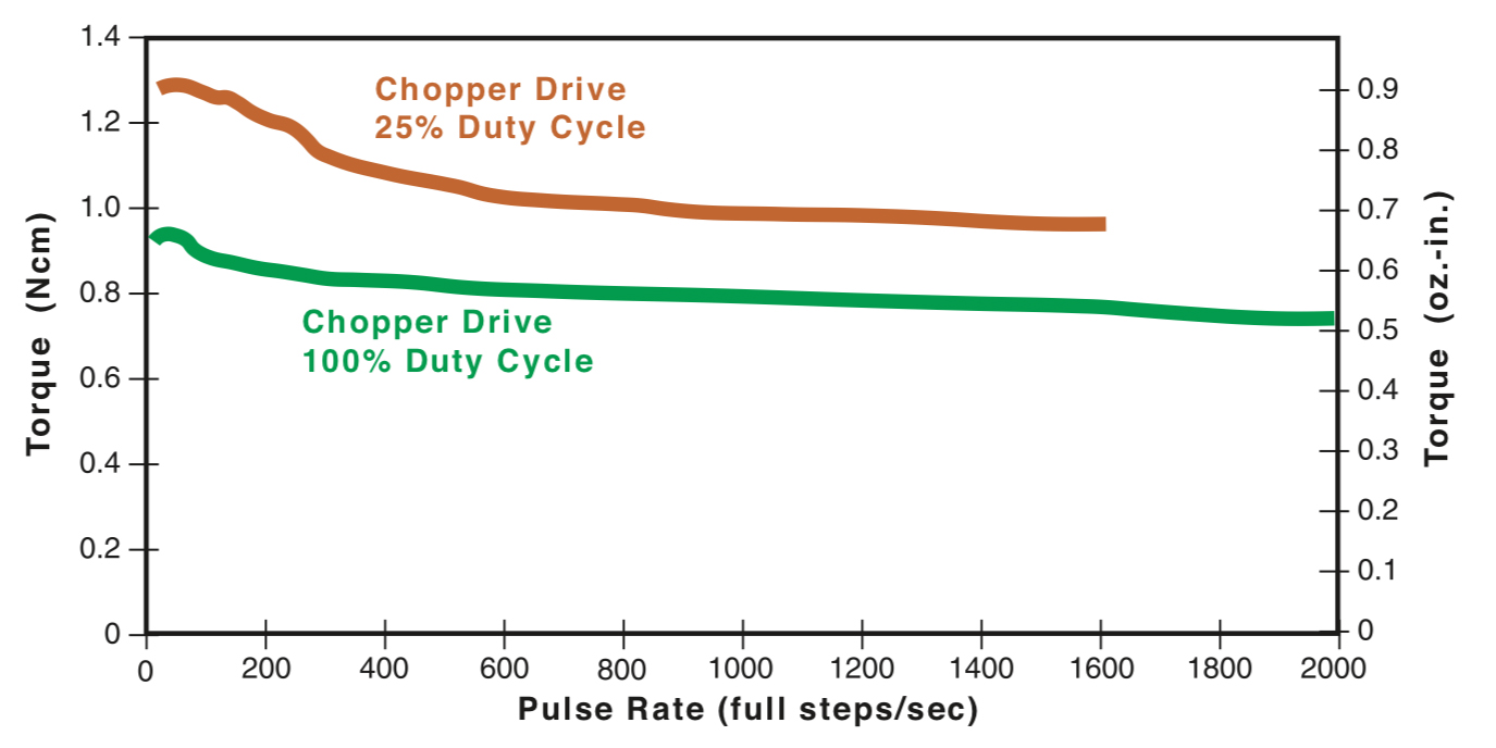
Image credit: AMETEK Inc.
Voltage chopping also modulates the width of the output pulses (pulse width modulation) and is typically done at a frequency of 20 kHz or higher — above the audible range. The impedance in the windings varies with the motor speed, so it plays a role in determining the voltage on-time.
At slow motor speeds — and low impedance — the chopper drive provides a short on-time for the voltage, producing a small pulse width. Alternatively, at high speeds —and high winding impedance — the chopper drive provides a long on-time for the voltage, producing a large pulse width and allowing time for the current to rise sufficiently to produce the rated torque.
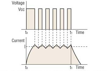
Image credit: Oriental Motor USA Corp.
A current-sensing resistor placed in series with each winding regulates the current and ensures the shortest time possible for current to build up and decline. As the current increases, voltage develops across the resistor. This voltage is monitored by a comparator, and at a predetermined reference voltage, the output voltage from the drive is turned off (chopped) until the next pulse occurs. This allows current to build and decline as the voltage is switched on and off.
By controlling the duty cycle of the drive through chopping, the average voltage and current are kept equal to the motor’s nominal voltage and current ratings. The result is precise torque control, and more importantly, higher torque production at high motor speeds.
Microstepping drives are common versions of chopper drives.
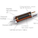
Feature image credit: AMETEK Inc.
Leave a Reply
You must be logged in to post a comment.