• Skip to primary navigation
  • Skip to main content
  • Skip to primary sidebar
  • Skip to footer

Motion Control Tips

Automation • Motion Control • Power Transmission

  • News
    • Industry News
    • Editor Blogs
    • Video
  • Controls
    • HMIs
    • PC-Based Controllers
    • PLCs + PACs
    • Stand-Alone Controllers
    • Software
  • Drives
    • Servo Drives
    • Stepper Drives
  • Encoders
    • Absolute Encoders
    • Incremental Encoders
    • Rotary Encoders
  • Mechanical
    • Bearings
    • Brakes + Clutches
    • Belt + chain
    • Couplings
    • Gears + Gearing
    • Lubrication
    • Shock + Vibration Mitigation
    • Springs + Rings + Seals
  • Linear
    • Actuators
    • Linear Motors
    • Linear Encoders
  • Motors
    • AC Motors
    • DC Motors
    • Brushless Motors
    • Gearmotors
    • Piezo Motors
    • Servo Motors
    • Stepper Motors
  • Systems
    • Conveyors + linear transport systems
    • Gantries + Stages
    • Rotary Tables
    • Grippers + End Effectors
    • Robotics
  • Networks
    • Connections + Sliprings
    • Fieldbuses
    • I/O
    • Sensors + Vision
  • FAQs
    • Motion Casebook
    • Motion Selection Guides
  • Suppliers
You are here: Home / Featured / Updated: Basics of compression springs for motion designs

Updated: Basics of compression springs for motion designs

July 25, 2018 By Lisa Eitel Leave a Comment

Engineers incorporate compression springs in motion designs that need linear compressive forces and mechanical energy storage — designs such as pneumatic cylinders and push-button controls, for example. The most conventional compression spring is a round metallic wire coiled into a helical form.

Photo courtesy Lee Spring
This compression spring has a barrel shape for lateral stability.

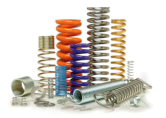
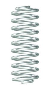
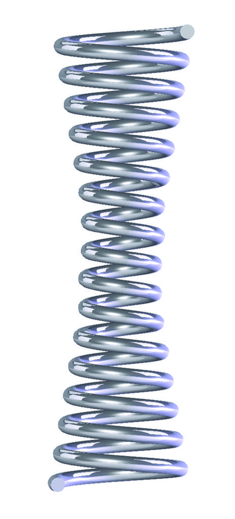
The most common compression spring, the straight metal coil spring, bends at the same diameter for its entire length, so has a cylindrical shape.

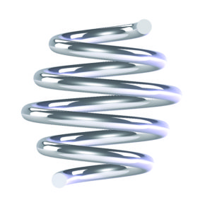
Cone-shaped metal compression springs are distinct in that diameter changes gradually from a large end to a small end; in other words, they bend at a tighter radius at one end.  Cone-shaped springs generally go into applications that need low solid height (the total height when compressed) and higher resistance to surging. Whether cylindrical or cone shaped, helical compression springs often go over a rod or fit inside a hole that controls the spring’s movement.

Other configuration types include hourglass (concave), barrel (convex), and magazine (in which the wire coils into a rectangular helix).

This compression spring has reduced ends.

Most compression springs have squared and ground ends. Ground ends provide flat planes and stability under load travel. Squareness is a characteristic that influences how the axis force produced by the spring can be transferred to adjacent parts.

Although open ends may be suitable in some applications, closed ends afford a greater degree of squareness.

Squared and ground end compression springs are useful for applications that specify high-duty springs; unusually close tolerances on load or rate; minimized solid height; accurate seating and uniform bearing pressures; and minimized buckling.

This concave (hourglass-shaped) compression spring can stay centered, even in large-diameter bores.

The key physical dimensions and operating characteristics of these springs include their outside diameter (OD), inside diameter, wire diameter, free length, solid height, and spring rate or stiffness.

• Free length is the overall length of a spring in the unloaded position.

• Solid height is the length of a compression spring under sufficient load to bring all coils into contact with adjacent coils.

• Spring rate is the change in load per unit deflection in pounds per inch (lb/in.) or Newtons per millimeter (N/mm).

The dimensions, along with the load and deflection requirements, determine the mechanical stresses in the spring.

When the design loads a compression spring, the coiled wire is stressed in torsion and the stress is greatest at the wire surface.

As the spring is deflected, the load varies, causing a range of operating stress. Stress and stress range affect the life of the spring.

The higher the stress range, the lower the maximum stress must be to obtain comparable life. Relatively high stresses may be used when the stress range is low or if the spring is subjected to static loads only.

The stress at solid height must be low enough to avoid permanent damage because springs are often compressed solid during installation.

You may also like:


  • Engineered materials and upfront design work (are leading trends for…

  • Power-transmission components and mechanical systems see three new trends

  • SPIROL ArmorGalv® — a 1,000+ hour corrosion-resistant coating for tubular…

  • Motion systems application examples: Compression springs

  • Design engineering guide to selecting compression springs

Filed Under: Featured, Mechanical PT, Springs + Rings + Seals

Reader Interactions

Leave a Reply

You must be logged in to post a comment.

Primary Sidebar

POWER TRANSMISSION REFERENCE GUIDE

DESIGN GUIDE LIBRARY

“motion
Subscribe Today

RSS Featured White Papers

  • Specifying electric rodless actuators: Ten tips for maximizing actuator life and system performance
  • The truth about actuator life: Screw drive survival
  • Top Ten Tips: How to specify electric rod-style actuators for optimal performance, reliability and efficiency

Footer

Motion Control Tips

DESIGN WORLD NETWORK

Design World Online
The Robot Report
Coupling Tips
Linear Motion Tips
Bearing Tips
Fastener Engineering.

MOTION CONTROL TIPS

Subscribe to our newsletter
Advertise with us
Contact us
About us
Follow us on TwitterAdd us on FacebookAdd us on LinkedInAdd us on YouTubeAdd us on Instagram

Copyright © 2022 · WTWH Media LLC and its licensors. All rights reserved.
The material on this site may not be reproduced, distributed, transmitted, cached or otherwise used, except with the prior written permission of WTWH Media.

Privacy Policy | RSS