Busbars are components that facilitate the distribution of power to electrical equipment, supplementing or replacing traditional wiring in applications such as commercial facilities, data centers, and industrial plants.
At their most basic, busbars are relatively simple bars, strips, or rods made of copper, brass, or aluminum, but in many cases, they’re constructed in specific shapes and dimensions to meet the user’s design and space requirements. They can also be plated with nickel or silver for corrosion protection, or coated to meet application-specific requirements. Laminated versions — in which layers of copper are separated by a thin dielectric (insulating) material and laminated into a single structure — can serve as additional structural support for the power distribution system.
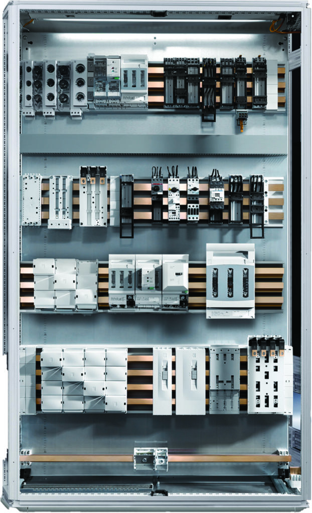
Image credit: Rittal
In industrial applications, busbars are primarily used for simplicity and cost-savings. Case in point: Busbars used in motor control centers or control cabinets can replace the wiring of numerous electrical components. This reduces the number of parts, and in turn, the amount of installation effort required, which also reduces the probability of assembly errors. Connecting electrical equipment via busbars also allows better organization of components in electrical enclosures, which saves valuable space and makes troubleshooting and correcting errors less time-consuming.
In addition to making installation and maintenance more efficient, busbars can improve the performances of variable frequency drives by minimizing inductance — which is important, due to the fast switching times of IGBTs (semiconductors) used in the inverter section of the drive — and by reducing switching losses. Lower inductance can also minimize harmful voltage spikes that cause ringing and can damage connected motors and cables.
In motion control applications, busbars are often used where multiple drives are fed by a common bus. For example, if multiple servo drives work together, a busbar system — able to withstand the high currents of the DC bus — can serve as the DC link and the 24 V power supply for all the drives. This eliminates a significant amount of wiring, improves reliability, and saves space in the control cabinet.
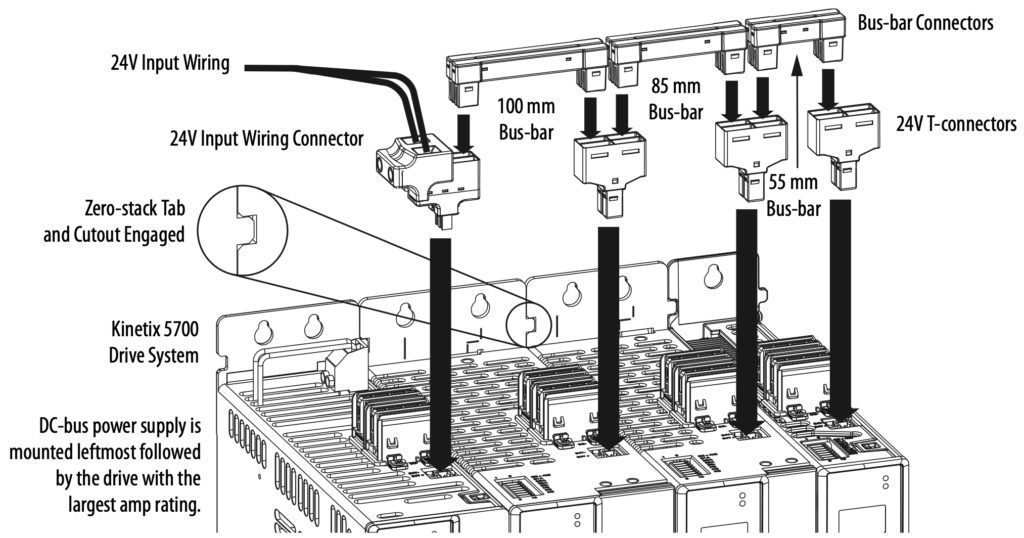
Image credit: Rockwell Automation
Selecting a busbar requires evaluating both its electrical and physical properties. And because current flowing through conductors creates interacting magnetic fields, busbars must also be able to withstand electrodynamic forces caused by these magnetic fields.
Key electrical properties of busbars include rated current, short-circuit current, rated voltage, and operating voltage. Important physical properties include the busbar’s cross-section, the distance between phases and between insulators of the same phase, and even joining methods — all of which can affect parameters such as the busbar’s resistance to the current flowing through it, its maximum operating temperature, and its temperature rise.
The amount of current a device can carry without exceeding its maximum operating temperature is sometimes referred to as ampacity.
Leave a Reply
You must be logged in to post a comment.