A common type of stepper drive is the chopper drive, so named because it rapidly switches the output voltage from the drive on and off — “chopping” it — to provide constant current to the motor. Chopper drives use one H-bridge per motor phase to drive voltage to the motor windings. A sense resistor at the bottom of the H-bridge monitors the current. When a set current level is reached, the H-bridge changes state to stop the current supply to the motor. After a set period of time (referred to as the “off time”), a new cycle begins, and the H-bridge once again drives current to the winding.
Although the H-bridge doesn’t supply current during the off time, current is maintained in the motor coils. While this stored current dissipates, or decays, it must have a path to flow through, or the field-effect transistors (FETs) in the H-bridge will be damaged. One option for a safe current path is to use freewheeling diodes in parallel with the FETs, but these add bulk and cost. Instead, the FETs themselves can be manipulated in one of two ways to provide a safe path for the decaying current.
An H-bridge is a circuit that contains four independently controlled switching elements (FETs) that direct the current flow to the load (in this case, the stepper motor).
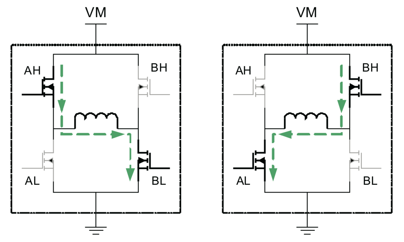
Image credit: Texas Instruments
Turning on two FETs on the same side of the H-bridge causes very high current (referred to as “shoot through”) that could damage the FETs. Therefore, when the FETs on one side of the H-bridge need to be turned on sequentially, a method referred to as “break before make” is used.
This method disables the first FET for a set amount of time (typically a few hundred nanoseconds) before the second one is enabled, preventing shoot-through. During this brief “dead time,” when neither FET is enabled, internal body diodes on the FETs carry the current.
Current decay: Fast or slow
The two methods of current decay using the FETs are termed “fast decay” and “slow decay.” It’s important to note that, in this context, the terms “fast” and “slow” refer to the speed at which current decays, and are inversely related to how quickly the motor stops.
With fast decay, negative voltage is applied to the winding by switching on the opposite FETs and reversing the direction of current flow through the H-bridge. Fast decay enables the motor to respond quickly to changing step inputs, but it results in a slow stop of the motor. The downside of fast decay is that it causes high current ripple.
Although fast decay doesn’t provide truly recirculating current (current flows back to the power supply), it is sometimes referred to as a type of recirculating current.
With slow decay, two of the FETs (either both high-side or both low-side) in the H-bridge are turned on. This shorts the motor winding and allows the current to recirculate and slowly decay according to the motor’s L/R time constant. In a DC motor, the slow decay method causes the motor to stop rapidly because it shorts the motor’s back EMF.
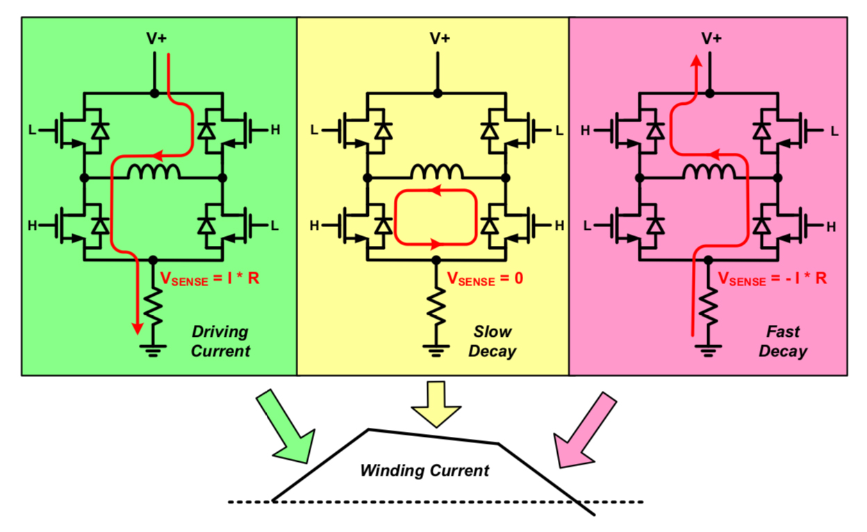
Image credit: Monolithic Power Systems
Microstepping drives find a compromise
Microstepping drives, which drive the motor windings with sinusoidal currents, typically use a method referred to as “mixed decay.” During the rising part of the current waveform, slow decay is sufficient to simulate the current sine wave as microsteps are issued, while providing high efficiency and low current ripple. But when the waveform is decreasing, slow decay doesn’t allow current to decrease fast enough to maintain the sinusoidal waveform, and fast decay would introduce unacceptable current ripple.
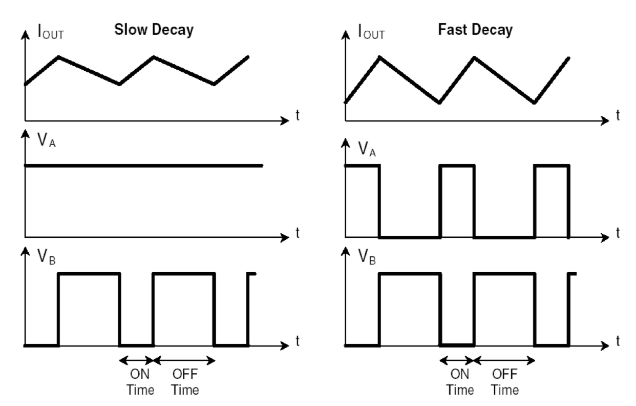
Image credit: STMicroelectronics
Mixed decay solves this problem by beginning the downward part of the current waveform with fast decay enabled, and then switching to slow decay. This maintains the sinusoidal shape of the current while minimizing current ripple.
Feature image credit: STMicroelectronics
Leave a Reply
You must be logged in to post a comment.