• Skip to primary navigation
  • Skip to main content
  • Skip to primary sidebar
  • Skip to footer
  • Advertise
  • Subscribe

Motion Control Tips

Automation • Motion Control • Power Transmission

  • News
    • Industry News
    • Editor Blogs
  • Controls
    • HMIs
    • PC-Based Controllers
    • PLCs + PACs
    • Stand-Alone Controllers
    • Software
  • Drives
    • Servo Drives
    • Stepper Drives
  • Encoders
    • Absolute Encoders
    • Incremental Encoders
    • Rotary Encoders
  • Mechanical
    • Bearings
    • Brakes + Clutches
    • Belt + chain
    • Couplings
    • Gears + Gearing
    • Lubrication
    • Shock + Vibration Mitigation
    • Springs + Rings + Seals
  • Linear
    • Actuators
    • Linear Motors
    • Linear Encoders
  • Motors
    • AC Motors
    • DC Motors
    • Brushless Motors
    • Gearmotors
    • Piezo Motors
    • Servo Motors
    • Stepper Motors
  • Systems
    • Conveyors + linear transport systems
    • Gantries + Stages
    • Rotary Tables
    • Grippers + End Effectors
    • Robotics
  • Networks
    • Connections + Sliprings
    • Fieldbuses
    • I/O
    • Sensors + Vision
  • Resources
    • FAQs
      • Motion Casebook
      • Motion Selection Guides
    • Suppliers
    • Video
You are here: Home / FAQs + basics / FAQ: What’s the difference between torque constant, back EMF constant, and motor constant?

FAQ: What’s the difference between torque constant, back EMF constant, and motor constant?

April 5, 2017 By Danielle Collins Leave a Comment

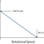
A DC motor’s output torque is directly proportional to the current through the windings, and the motor’s angular speed is directly proportional to the back EMF that it generates. These simple relationships are typically given by the equations:

motor constant

Where:

T = torque (Nm)

I = current (A)

kT = torque constant (Nm/A)

And

Where:

ω = angular velocity (rad/s)

VE = back EMF voltage (V)

kE = back EMF constant (V-s/rad)


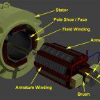
The torque constant, kT, is specific to motor’s design, including its magnetic strength, number of wire turns, and armature length. The slope of the motor’s torque-current curve is determined by the torque constant.

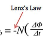
The back EMF constant, kE, represents the relationship between the motor’s back EMF and its speed. It has an often-used inverse, referred to as the voltage constant, kV. The back EMF constant, kE, is given in units of volt-seconds per radian (V-s/rad), and conversely, the voltage constant, kV is given in units of radians per volt-second (rad/V-s).

Interestingly, the torque constant, kT and the back EMF constant, kE are equal. This can be demonstrated by applying the law of conservation of energy: electrical power in must be equal to mechanical power out plus motor electrical losses.

DC motor
Typical DC motor circuit
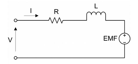
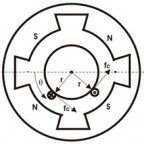
Image credit: Precision Microdrives Limited

Electrical power in is equal to voltage times current.

motor constant

According to Kirchhoff’s Voltage Law, the applied voltage is given as:

motor constant

Where:

R = motor resistance (ohms)

Substituting for VE (from above)

motor constant

Now, multiplying voltage by current, we get:

motor constant

Mechanical power out is equal to torque times rotational speed:

motor constant

Substituting for T (from above):

motor constant

Electrical losses are caused by the resistance in the circuit:

motor constant

Now, setting electrical power in equal to mechanical power out plus losses, we get:

motor constant

You can see that all terms cancel out, except the back EMF constant and the torque constant, which must be equal:

motor constant


Also related to the torque constant is the motor constant, km, which represents the motor’s ability to convert electrical power to mechanical power. The motor constant is given by:

motor constant

Where:

km = motor constant (Nm/√Watt)

T = torque (Nm)

P = resistive power losses (also known as I2R losses) (W)

Substituting for T (from above) and resistive power losses, P, we get:

motor constant

Which simplifies to:

motor constant

The motor constant is supplied by the manufacturer, and is useful for comparing the relative outputs, or efficiencies, of different motors.

You Might Also Like

Filed Under: DC Motors, FAQs + basics, Featured, Motors

Reader Interactions

Leave a Reply

You must be logged in to post a comment.

Primary Sidebar

LEARNING CENTER

Design World Learning Center

Motion Control Handbook

“mct
EXPAND YOUR KNOWLEDGE AND STAY CONNECTED
Get the latest info on technologies, tools and strategies for Design Engineering Professionals.

RSS Featured White Papers

  • Robotic Automation is Indispensable for the Logistics Industry’s Continued Growth and Success
  • Reliable Linear Motion For Packaging Machines
  • Polymers Outperform Metals In Precision Gearing

Footer

Motion Control Tips

DESIGN WORLD NETWORK

Design World Online
The Robot Report
Coupling Tips
Linear Motion Tips
Bearing Tips
Fastener Engineering.
Wire and Cable Tips

MOTION CONTROL TIPS

Subscribe to our newsletter
Advertise with us
Contact us
About us

Copyright © 2025 · WTWH Media LLC and its licensors. All rights reserved.
The material on this site may not be reproduced, distributed, transmitted, cached or otherwise used, except with the prior written permission of WTWH Media.

Privacy Policy | RSS