
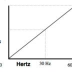
Variable frequency drives control AC induction motors through one of several control schemes. Scalar control (also referred to as V/Hz or V/f control) varies both the voltage and frequency of power supplied to the motor to maintain a fixed ratio between the two. This keeps the strength of the magnetic field at a constant level so that torque production remains stable. Scalar control is a simple, inexpensive control method, but it doesn’t allow precise control of motor speed.
Vector control (also referred to as field oriented control, or FOC) controls the magnetizing and the torque-producing components of the stator current independently to control both motor speed and torque.
Another control method, known as direct torque control (DTC), is similar to field oriented control, in that it decouples torque and flux and controls them independently. But DTC controls motor torque directly, without a modulator, so torque response is much faster.
Direct torque control uses two control loops — a speed control loop and a torque control loop — that work together, along with an advanced motor model, to precisely predict stator flux and motor torque. Here’s how it works:
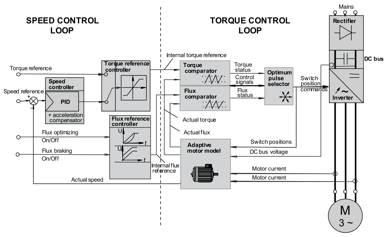
1 – Two motor phase currents and the DC bus voltage are measured, along with the inverter’s switch positions. (Motor voltage is determined from the DC bus voltage and the inverter’s switch positions.)
2 – Motor current and voltage are fed to the motor model, which uses advanced mathematical algorithms to produce exact values of the stator flux and motor torque, along with shaft speed, every 25 μs (as fast as 12.5 μs in some drives).
3 – The actual torque and flux values are fed to the torque and flux comparators, which compare them to torque and flux reference values that are provided by the speed control loop (see #6).
The goals of the comparators are to hold the magnitudes of the torque and flux vectors within a narrow hysteresis band around the reference values. This is a primary factor in DTC’s ability to achieve fast torque response without overshoot.
4 – Torque and flux status signals are fed to the optimum pulse selector.
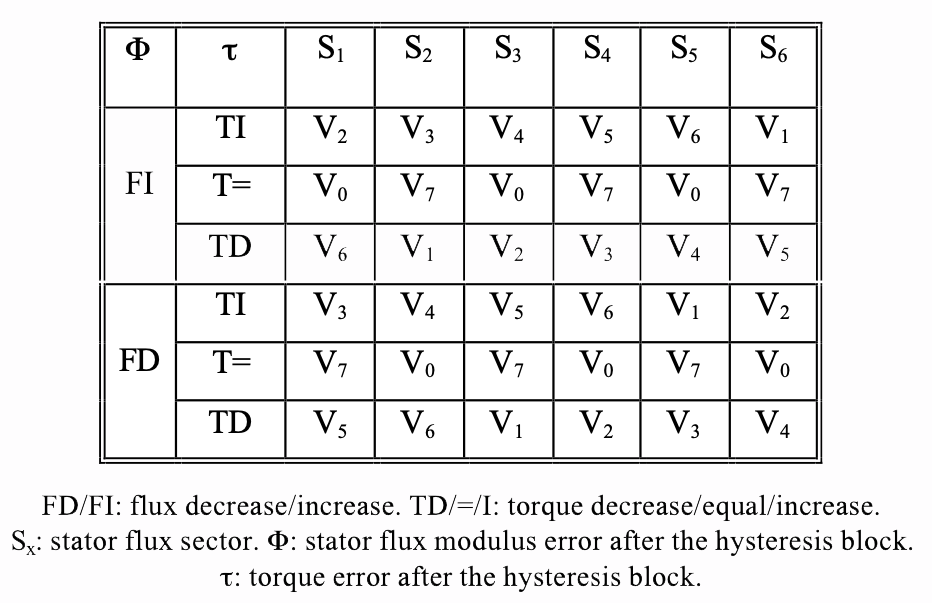
5 – The optimum pulse selector chooses the optimum voltage vector from a lookup table and, based on this, sends pulses to the inverter’s semiconductor switching devices to maintain or change the motor torque as required.
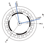
The lookup table provides the optimum voltage vector based on three parameters: whether torque and stator flux each need to be increased or decreased (or, for torque, held constant), and in which sector (60 degree segment) of the space vector plane the stator flux resides.
The semiconductor switching in the inverter again determines motor voltage and current, which determines motor torque and flux, therefore closing the control loop.
6 – The speed control loop contains a speed controller (which consists of a PID controller and an acceleration compensator), a torque reference controller, and a flux reference controller.
The output of the speed controller is fed to the torque reference controller, whose output is the internal reference value for the torque comparator in the torque control loop.
The flux reference controller determines an absolute stator flux value and provides this as the internal reference for the flux comparator in the torque control loop. The flux reference controller is also where flux is controlled and modified to enable inverter functions such as energy optimization and flux braking.
When direct torque control is compared to field oriented control, which also allows tight control of motor speed and torque, two primary differences stand out. First, direct torque control is sensorless — no speed or position encoders are required. It only requires voltage and current measurements. This reduces cost and improves reliability.
The second difference is that direct torque control doesn’t require a modulator (pulse-width modulator, or PWM), so processing time is reduced by a factor of 10, which improves torque response, typically to less than 2 ms. This means torque and speed can be accurately controlled even at low speeds, and full start-up torque is available all the way down to zero speed.

Leave a Reply
You must be logged in to post a comment.