
One common, modern method for controlling three-phase induction motors and permanent magnet synchronous motors (aka BLAC or PMAC motors) is field oriented control, which independently controls the magnetizing and torque-producing components of the stator current. This allows the torque-producing component to be kept orthogonal to the rotor flux, maximizing torque production.
Space vector pulse width modulation (SVPWM) is a technique used in the final step of field oriented control (FOC) to determine the pulse-width modulated signals for the inverter switches in order to generate the desired 3-phase voltages to the motor.
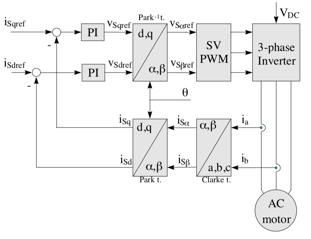
Image credit: Texas Instruments
The following is a summary of how FOC with SVPWM operates:
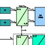
1) Measure two of the three motor phase currents and feed them into a Clarke transform to convert them from a three-phase system (ia, ib, ic) to a two-dimensional orthogonal system (iα, iβ). Note that it’s not necessary to measure all three currents, since the sum of the three must equal unity (0). So the third current must be the negative sum of the first two.
2) Apply a Park transform to convert the two-axis stationary system (iα, iβ) to a two-axis rotating system (iq, id), where the d axis current is aligned to the rotor flux and the d axis current (the torque-producing component) is orthogonal to the rotor flux.
3) The stator current flux and torque are controlled independently, typically by PI controllers. Voltages to be applied to the motor, Vd and Vq, are determined from the PI controllers.
4) Next, an inverse Park transform converts the two-axis rotating system (Vsqref, Vsdref) back to a two-axis stationary system (Vsαref, Vsβref). These are the components of the stator voltage vector and are the inputs for the SVPWM, which generates the 3-phase output voltage to the motor. (Note that the use of SVPWM eliminates the need for an inverse Clarke transform to obtain the three-phase output voltages.)
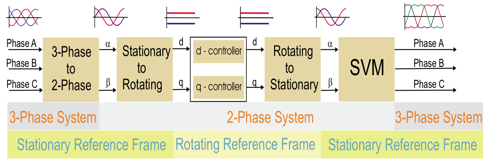
Image credit: Freescale Semiconductor
The details behind SVPWM
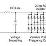
Voltage is delivered to the motor by a three-phase inverter with six transistors (two on each leg of the output). Each of the three outputs can be in one of two states (top transistor closed and bottom transistor open, or vice-versa), giving eight (23) total states for the output. These are referred to as base vectors.
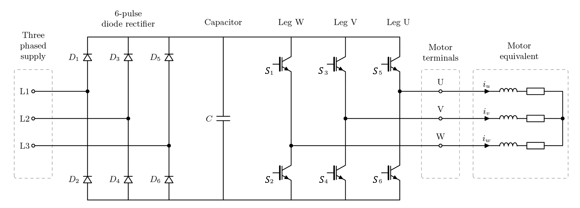
Image credit: switchcraft.org
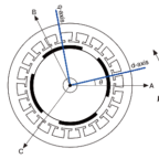
The eight base vectors are plotted on a hexagonal star diagram. Each vector makes up a spoke of the star, with 60 degrees phase difference between adjacent vectors. The two vectors (V0 and V7) that contain outputs which are either all plus or all minus are referred to as null vectors and are plotted at the center (origin) of the star.
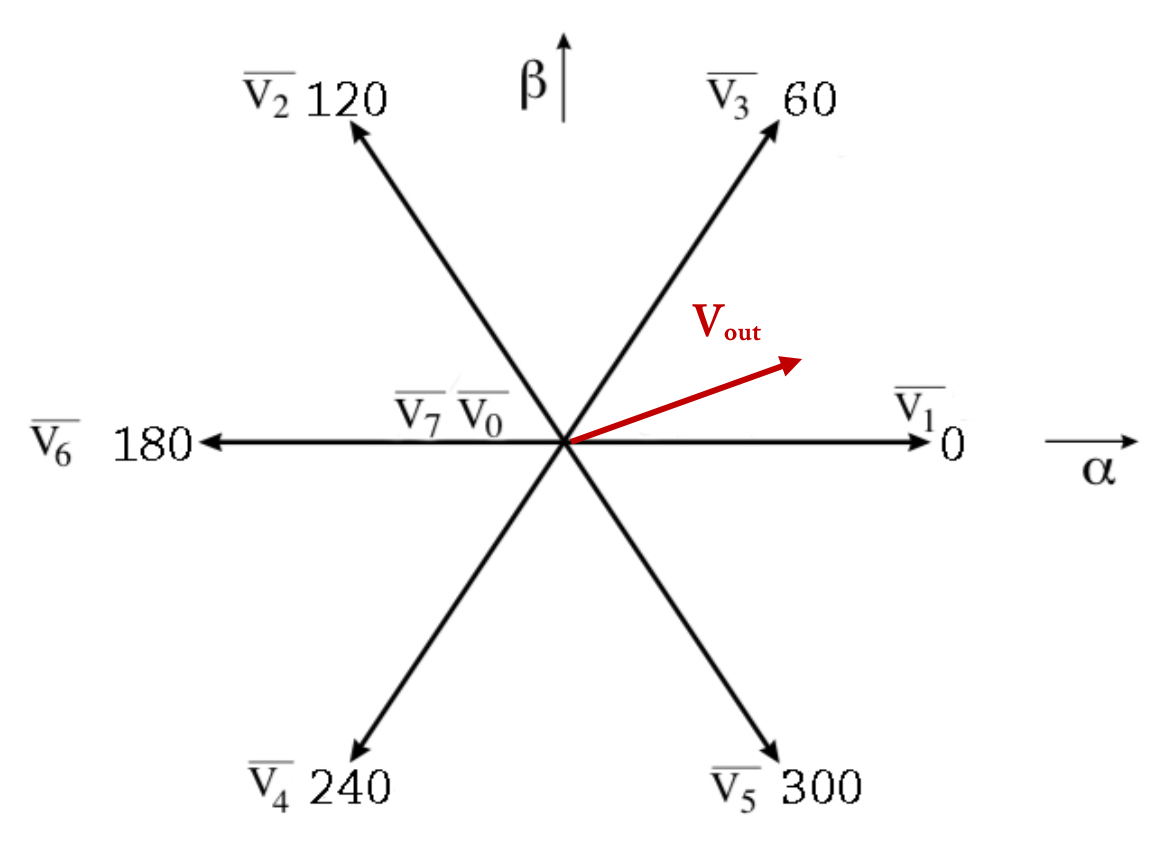
The goal of SVPWM is to produce a “mean vector” during the PWM period (TPWM) that is equal to the desired voltage vector (Vout).
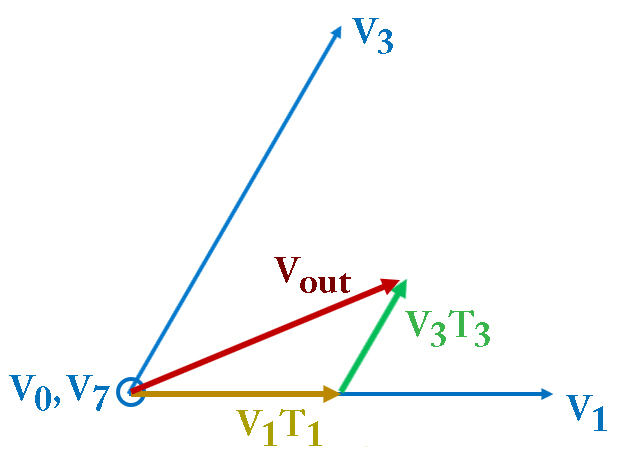 The location of Vout is determined on the star diagram, and the base vectors that constrain that sector (V1 and V3, for example), along with one of the null vectors, are used to synthesize the desired voltage. This is done by applying V1 for a specified time (T1), V3 for a specified time (T3), and the null vector for the amount of time necessary (T0) to provide a resultant vector equal to Vout.
The values of T1, T3, and T0 can be determined with the following equations:
![]()
The simulation of Vout can then be expressed as:
![]()
Compared to standard field oriented control, using FOC with space vector pulse width modulation enables more efficient use of the DC supply voltage, provides lower harmonic distortion — which improves power factor — and reduces torque ripple.
Leave a Reply
You must be logged in to post a comment.