
The basic function of a servo drive is to convert, or amplify, low-power signals from the controller into higher-power signals to be delivered to the motor windings. Servo drives (also referred to as servo amplifiers) can be either linear or switching types, depending on how power is delivered to the motor from the switching devices (typically IGBTs or MOSFETs) in the inverter section of the drive.
A linear servo amplifier allows voltage to flow continuously to the motor by keeping the transistors in the inverter section of the drive always on to some degree. In contrast, a switching, or PWM (pulse-width modulation), amplifier switches the transistors in the inverter section on-and-off to modulate the voltage flowing to the motor.
So why use a switching, or PWM, drive rather than a linear drive? The primary reason is efficiency. Because the transistors in a linear drive are always on, they experience high power dissipation and, in turn, can generate significant heat. This reduces efficiency and increases size, since the drive needs a suitable heat sink or cooling mechanism to protect the transistors.
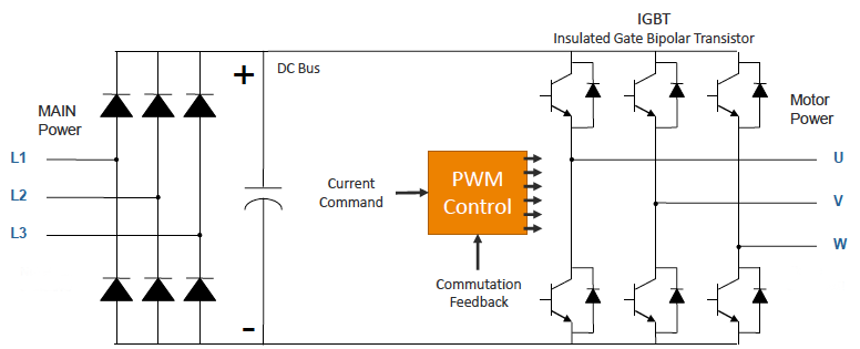
Image credit: M. Pelletier, Yaskawa
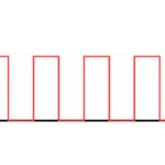
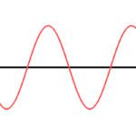
PWM drives switch the transistors on-and-off at a very high frequency — typically 10 to 20 Hz — creating a train of square-wave pulses that simulates an analog, sine wave signal.
The duty cycle of the pulses — the ratio of on-time to total switching time (on time + off time) — determines the pulse width, which in turn, determines how much voltage and current are delivered to the motor.
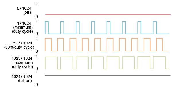
Image credit: Performance Motion Devices
Because the transistors in a PWM drive operate in their linear, or active, region — in other words, they’re either fully on or fully off — power dissipation and heat generation are relatively low, especially when compared to carrier-based PWM. And the faster switching times of PWM improve efficiency because the transistors spend less time in their linear region. However, this quick switching causes a high dv/dt (change in voltage), which can result in undesirable effects such as noise that interferes with other equipment and over-voltages known as reflected waves, so proper filtering methods and cable shielding should be implemented.
The pulses for a PWM drive can be created in one of two ways. In the traditional method, often referred to as carrier-based PWM, the PWM pulses are created using the triangular signal that represents the switching frequency of the inverter, together with a sine wave signal produced by the PWM generator.
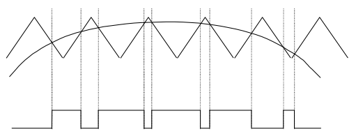
Image credit: Rockwell Automation
A more advanced method for creating the PWM pulses is known as space vector modulation, or SVM (sometimes referred to as space vector pulse width modulation, or SVPWM). This method uses vector representations of the three-phase voltages and calculates the required duty cycle of inverter switches to synthesize a reference output voltage. (This article explains the theory and operation of space vector modulation in more detail.) Space vector modulation makes better use of the bus voltage, delivering higher voltage to the motor with lower total harmonic distortion and less torque ripple.
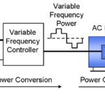
Variable frequency drives (VFDs) for AC induction motors also use PWM methods to deliver voltage to the motor. In these applications, the drive manipulates both the duty cycle and the frequency of the pulses, to control the voltage and the motor speed.
Leave a Reply
You must be logged in to post a comment.