Servo systems experience resonance due to compliance or backlash in mechanical components such as gearboxes, screw drives, and couplings. Resonance reduces system performance, can cause audible noise, and in extreme cases can even damage hardware. Servo tuning is the process of setting controller gains to optimize servo performance, but as gains are increased, resonances typically increase, both in number and in severity.
Mechanical resonance occurs when the natural frequency of the system is excited. When servo feedback includes components of the system’s natural frequency, the amplification inherent in the natural frequency is compounded by the controller gain, which can cause severe vibration and instability in the servo loop.
Options to reduce resonances include mechanical solutions, such as using stiffer couplings, shafts, and drive components (screw, belt, gearbox), but this can be difficult to achieve while maintaining performance and cost goals. Another option is to reduce the load-to-motor inertia ratio, either by changing the load parameters, by using a higher inertia motor, or by using a higher reduction gearbox. But load parameters are difficult to change, higher inertia motors (which are typically larger) require additional torque, and other factors play a role in the selection of a gear ratio – making these options less than ideal or simply not feasible.
From a servo tuning standpoint, resonance can be reduced or eliminated by lowering the control gains. However, this compromises the performance of the servo system by reducing its bandwidth, and therefore, its responsiveness. The simplest method to reduce resonance, while keeping control gains as high as possible, is to add filters to the control loop.
Resonances can be classified as high-, mid-, or low-frequency, depending on how close they are to the control loop bandwidth (above, near, or below, respectively). Most servo systems experience high-frequency resonances, which manifest as a high-pitch squealing noise. Two types of filters commonly used for high-frequency resonances are notch filters and low pass filters.
Notch filters
Notch filters attenuate, or decrease the magnitude of, a specific, narrow range of frequencies around a center frequency (notch). Frequencies above or below the specified range are passed through unaltered – hence, the other term for a notch filter is a “band rejection filter.” Signals near the notch (center) frequency are heavily attenuated, but attenuation drops off at either end of the specified range.
One drawback to notch filters is that they are not effective if the resonant frequencies change significantly. Changes in resonant frequency can be caused by changes in load inertia – for example, in a dispensing application, the load changes as the product is dispensed. They can also change as compliance and backlash increase as mechanical components “wear in” and connections become looser or backlash increases.
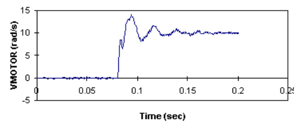
Image credit: Kollmorgen/IEEE
Low-pass filters
Low-pass filters attenuate high-frequency signals that occur above their bandwidth, while passing low-frequency signals through unaltered. However, because they work on the high-frequency response of the system, they can reduce servo system performance. And if the problem frequencies are low, using a low-pass filter whose bandwidth is near the servo response can cause instability in the servo system.
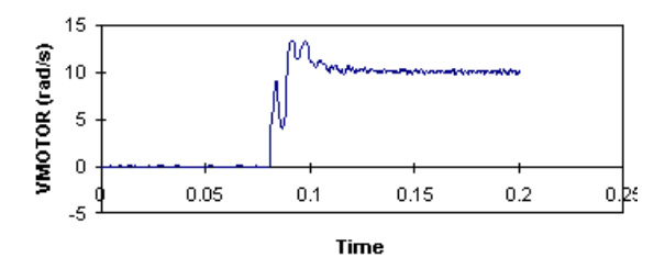
Image credit: Kollmorgen/IEEE
Most solutions to resonance problems employ one or more notch filters together with a low-pass filter. Some servo drives configure filter parameters in their “auto tuning” functions. In cases where filters have little effect on resonance (typically at frequencies below 500 Hz), other drive functions, such as vibration suppression, can be helpful in reducing the manual labor of tuning and setting filter parameters.
The type of resonances described here are referred to as “motor side resonances” because they are reflected back to the motor and captured by the encoder. This means they can be reduced or eliminated by tuning the control loop gains and applying filters.
Another type of resonance is referred to as “load side resonance.” These resonances are caused when the load or end effector oscillates due to compliances in its connection to the drive train and motor. Load side resonances are not typically captured by the encoder and, therefore, are not affected by servo loop tuning or filtering. Load side resonances are especially common in robots, cranes, and other designs with highly cantilevered loads.
Feature image credit: Panasonic Electric Works Europe AG



Leave a Reply
You must be logged in to post a comment.