by Todd Shudarek, Principal Engineer, MTE Corporation
A new filter for adjustable speed drives handles both differential and common mode problems.
Most users of pulse width modulation (PWM) ac drives are familiar with the elevated differential mode motor voltages due to the reflected wave phenomenon, fast rise times and peak voltages they can produce. However, many users are less familiar with common mode voltages produced by a PWM inverter that can also result in high voltages and peak currents to ground. Many of the problems associated with common mode voltages and currents are, by nature, not easy to locate. The common mode effects are associated with difficult to define parasitic parameters of cables and motors. Because these values do not in any way contribute to the normal operation of a drive, they are unpublished. However, they can cause erratic behavior of a controller board that can give a time-out error. Sometimes a ground fault error will occur and prevent the drive from starting. At the most catastrophic level, ringing of the common mode voltages and currents can cause premature failure of the motor bearings, motor windings or cables.
PWM drive common mode signals
Common mode voltages and currents that exist on the output of a typical PWM drive are inherent to the switching topology.
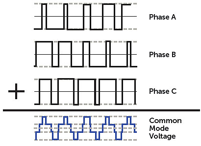
To understand this further, you need to examine the three-phase waveforms generated by a typical PWM drive. The three phases and the dc bus voltage can only be switched on or off by the IGBTs. Ideally, all the phases could sum together like three-phase sinusoidal waveforms and result in no common mode voltage. Inherently, they can never sum to zero during operation because the only time an odd number of switched waveforms can sum to zero is if all of them are turned off.

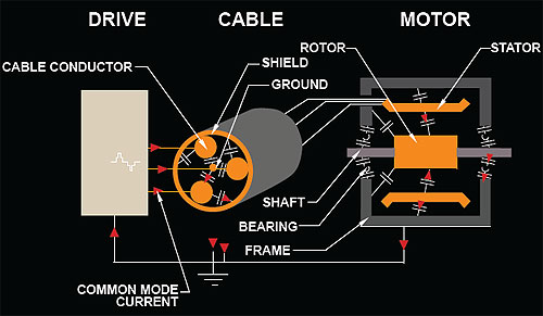
The common mode voltage produced by the typical PWM drive induces common mode currents that travel through parasitic capacitances located in the cable and motor. These currents can travel throughout the motor from the stator to the frame through the motor bearings to ground.
Common mode voltages and currents can sometimes cause system problems. These problems are difficult to diagnose as they appear as erratic time-out or ground fault errors. In extreme cases, the common mode ringing can result in premature failure of the motor bearings, motor windings or cables. These failures are both nuisances and problematic, causing loss of productivity.
Many solutions to these common mode voltages and currents have been introduced in the market. For instance, a common mode inductor can reduce the effects of these currents. Another possible solution is a shaft grounding kit, which provides protection for the bearings, but all common mode currents throughout the system are not reduced.

Although a shaft grounding brush is not a filter, it’s still a common method of protecting motor bearings. A properly installed shaft grounding brush can protect the motor bearings by providing an alternate current path, bypassing the motor bearings. This bearing protection, although quite effective at protecting the motor bearings, can exacerbate other problems. Because it creates a low impedance path to ground, ground currents can increase, thereby worsening other problems such as the issues of erratic controller board behaviors and ground faults. The shaft ground brush solution also does not offer any protection against the elevated differential mode voltages and rise times that even the most typical dV/dt filter provides.
Typical inductor topologies
There are basically two integrated inductor topologies in use for output filtering on PWM drives: a three-phase inductor (reactor) and a common mode inductor. Users typically use dV/dt filters that are constructed with a three-phase reactor that only provides differential mode filtering. In some circumstances, when there continues to be unexplained drive problems, users will attempt to remedy the situation by installing a common-mode inductor.
Common-mode inductors can be difficult to size, difficult to install and may not be effective because they may cause system resonance. The two inductor topologies either provide all differential mode filtering, or all common mode filtering, but not both.
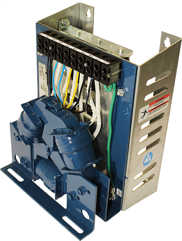
An ideal solution is to have a filter that provides differential mode and common mode mitigation, all in one filter. The recently developed dV Sentry filter from MTE contains a Triple Defense Core, a three-phase patented reactor construction that has both differential mode and common mode filtering.
A representative filter, the MTE Sentry DVS0065E, was tested with a 480 V, 50 hp drive system with 1,000 ft. of cable, full load, and an 8 kHz switching frequency. The differential mode filtering performed well, keeping the peak line-to-line motor voltage to less than 1,000 V, reduced the rise time and provided superior common mode filtering. The peak-to-peak common mode current was reduced from 15.9 A without a filter to 8.5 A with the MTE dV Sentry filter, a 47% reduction in peak common mode currents.

A typical dV/dt filter does not filter common mode currents. By design, they filter the differential mode caused by PWM inverters. In such system designs, an additional common mode choke can sometimes help, as well as the use of a shaft grounding kit on the motor.
Main takeaways
Common mode problems can cause erratic errors resulting in an operational time-out, ground fault error and sometimes prevent a drive from starting. At the most catastrophic level, ringing of the common mode voltages and currents can cause premature failure of the motor bearings, windings or cables. Look for a filter that provides reliable common and differential mode filtering to protect the motor.
MTE Corporation
www.mtecorp.com


Leave a Reply
You must be logged in to post a comment.