
Most linear motion devices have a rotary equivalent, and voice coil actuators are no exception. While the versions depicted in most product images and videos are linear, rotary voice coil actuators fill a need for smooth, arc-shaped motion and torque production with fast response times. But unlike the design relationship between rotary and linear motors, developing a rotary voice coil actuator isn’t simply a matter of taking the linear version and rolling it into a cylinder. While their components are the same, the configurations of linear and rotary voice coil actuators are quite different.
Voice coil actuators work on the principle of the Lorentz force, which is the force generated when a current-carrying conductor is placed in a magnetic field. In the case of a voice coil actuator, the magnetic field is created by permanent magnets and the conductor is a coil of wire. When current is applied to the coil, a force is generated, and the magnitude of the force is proportional to the applied current. (All other variables in the force production, such as magnetic flux and length of wire, are fixed for a given voice coil design.)
F = k*B*L*I*N
F = force (N)
k = force constant
B = magnetic flux density (tesla)
L = length of wire (m)
I = current (amps)
N = number of conductors
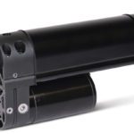
The most common linear voice coil actuator design features a moving coil, although the actuator can be constructed so that either the coil or the magnet is the moving part. In the moving coil design, a stationary cylindrical permanent magnet produces a radial magnetic field. Housed inside the permanent magnet cylinder is a coil that is wrapped around a non-conducting structure, or holder. The permanent magnet is housed in a ferromagnetic cylinder that is open at one end and has a “core” through its middle, which is necessary for completing the magnetic circuit. The coil assembly rides in the air gap between this core and the interior surfaces of the permanent magnet. Although it sounds complicated, the construction is actually quite simple, as shown below.
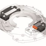
A rotary voice coil actuator is sometimes referred to as a “flattened” version of the linear design described above. In other words, to transform a linear voice coil actuator into a rotary version, place the linear voice coil actuator lengthwise on a table (as it would sit if it were operating horizontally) and flatten it into an essentially 2-D object. Then bend the ends so that it forms an arc (like a piece of macaroni). Now you have a rotary voice coil actuator.
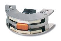
Image credit: BEI Kimco
Rotary versions provide torque rather than force. Similar to their linear counterparts, the amount of torque generated is proportional to the applied current, and the direction of the current determines the direction of motion. Excursion angles are typically less than 180 degrees, and commonly fall between 15 and 60 degrees.
Voice coil actuators are, technically, non-commutated DC motors. The term “voice coil” is often used because one of their first applications was to vibrate the paper cones in loudspeakers. Rotary voice coil actuators are also referred to as “arc segment” actuators or “limited angle torque motors” because they produce arc-shaped motion.
One of the strengths of voice coil actuators is their extremely smooth, cog-free motion with no torque ripple. This makes rotary versions ideal for applications that require high torque and quick response, such as gimbal positioners. They are also well-suited for moving optics and for controlling stabilization devices.
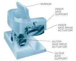
Image credit: BEI Kimco
Feature image credit: H2W Technologies, Inc.

Leave a Reply
You must be logged in to post a comment.