
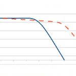
One of the most important tools for sizing a servo motor is the motor’s torque-speed curve, which shows the combinations of torque and speed that the motor can produce in two operating zones — continuous operation and peak, or intermittent, operation.
To prevent thermal overload of the motor — and the drive — it’s important to ensure that the application remains within the continuous duty zone of the torque-speed curve during normal operation and that it falls within the intermittent duty zone when peak torque is required.
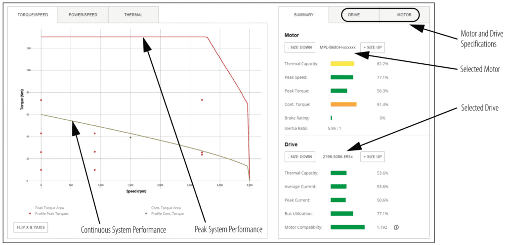
Image credit: Rockwell
The continuous duty zone represents the combinations of torque and speed that the motor can produce indefinitely without overheating. Because servo system move profiles are dynamic — requiring a range of speeds and torques throughout the move — the application’s RMS torque is used to determine whether the motor remains within the continuous duty zone of the torque-speed curve.
The RMS, or root-mean-square, torque is the amount of torque that, if applied constantly, would result in the same amount of motor heating as all the various torque requirements of the application during its move profile.
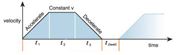
This includes the torque due to acceleration, torque during constant velocity, torque during deceleration, and torque during dwell — which can typically be assumed to be zero, unless the application requires torque to hold a load in place against a force — for example, holding a load against gravity in a vertical application.
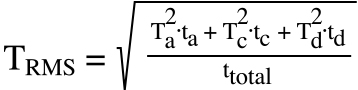
TRMS = root mean square torque (Nm)
Ta = torque required during acceleration (Nm)
ta = time for acceleration (s)
Tc = torque required during constant velocity (Nm)
tc = time at constant velocity (s)
Td = torque required during deceleration (Nm)
td = time for deceleration (s)
ttotal = total duty cycle time (s)
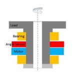
The torque required during the constant velocity portion of the move includes the amount of torque required to drive the load, the torque required to overcome any preload in the bearings or drive mechanism, and the torque required to overcome any additional friction in the system — for example, due to support bearings or seals.
![]()
Tc = torque required during constant velocity (Nm)
Td = torque required to drive the load (Nm)
Tp = torque required to overcome preload (Nm)
Tf = torque required to overcome friction (Nm)
The torque required during the acceleration part of the move includes the torque required during constant velocity plus the torque required to accelerate the load.
![]()
Ta = torque required during acceleration (Nm)
Tc = torque required during constant velocity (Nm)
Tacc = torque required to accelerate the load (Nm)
The torque required to accelerate the load depends on the total inertia of the system and its angular acceleration.
![]()
Tacc = torque required to accelerate the load (Nm)
Jt = total system inertia (kgm2)
α = angular acceleration (rad/s2)
The system inertia includes the inertia of the motor (which, at this point, will need to be estimated, since a specific motor hasn’t yet been chosen), the inertia of the drive mechanism — such as a ball screw or belt drive — and the inertia of the load.
![]()
Jt = total system inertia (kgm2)
Jm = inertia of the motor (kgm2)
Js = inertia of drive mechanism (kgm2)
Jl = inertia of the load (kgm2)
The angular acceleration is the maximum angular velocity divided by the time to accelerate.
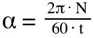
α = angular acceleration (rad/s2)
N = angular velocity (rpm)
t = acceleration time (s)
The torque required for the deceleration part of the move is simply the torque required for constant velocity minus the torque required for acceleration.
![]()
Td = torque required during deceleration (Nm)
Tc = torque required during constant velocity (Nm)
Tacc = torque required to accelerate the load (Nm)
The intermittent, or peak, duty zone represents the highest amount of torque the motor can produce at a given speed for a limited amount of time — typically a few milliseconds — as specified by the manufacturer.
To determine whether the application operates within the motor’s intermittent zone, we use the peak torque — the highest amount of torque the motor will need to produce during its duty cycle.
Peak torque typically occurs during acceleration, so we use the acceleration torque defined earlier — torque required for constant velocity plus the torque required for accelerating the total system load (motor, load, and drive mechanism).
![]()
Ta = torque required during acceleration (Nm)
Tc = torque required during constant velocity (Nm)
Tacc = torque required to accelerate the load (Nm)
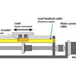
Two common drive types for linear motor applications are ball screws and belt and pulley systems. This article shows how to calculate the motor drive torque for ball screw driven systems, and this article explains how to calculate the motor drive torque for belt driven systems.

Leave a Reply
You must be logged in to post a comment.