
In servo-driven systems, feedback for position, velocity, and/or torque control is typically provided by a rotary encoder or resolver mounted to the motor. But mechanical components and connections in the drivetrain — such as gearboxes, ball screws, and couplings — are not perfectly rigid and introduce backlash, compliance, and windup into the system. This lack of rigidity causes a discrepancy between where the load “should” be based on the position of the motor shaft, and where the load is actually located. If the servo control system is based only on the motor feedback, the desired position may never be reached, and the system can experience instabilities such as oscillations and hunting.
In systems that exhibit backlash, compliance, and windup (that is, virtually all motion systems) but that also need very accurate position control, a second encoder is required to directly measure the position of the load. This method of using two feedback devices — one on the motor and one located at the load — is typically referred to as dual-loop control, or dual-loop feedback.
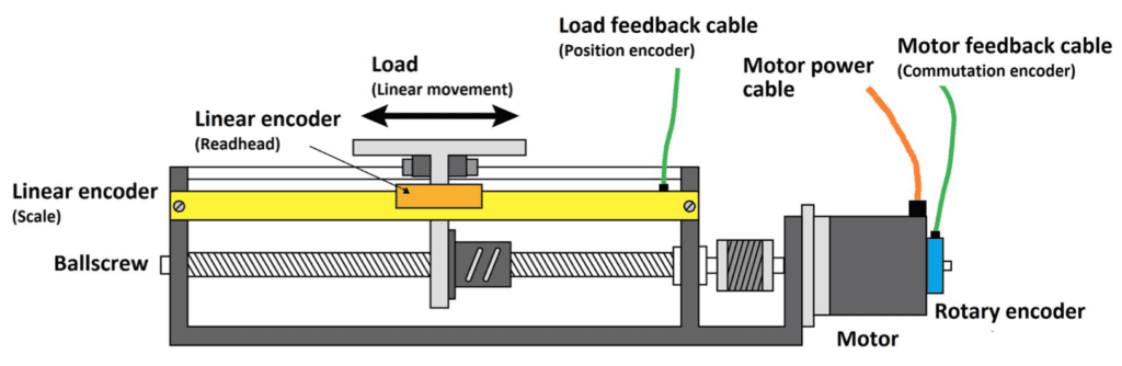
Image credit: ABB
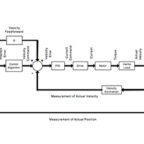
There are several methods of operation with dual-loop control, but in the most basic method, the controller first closes the inner loop, which is the velocity control loop. The velocity control loop receives feedback from motor encoder, and this feedback determines the appropriate velocity feedback gain (Kv), which imparts a damping effect on the system to reduce oscillations.
Note that velocity feedback gain (Kv) is similar to derivative gain (Kd), except that velocity feedback scales only the velocity measured by the motor encoder, whereas derivative gain scales the derivative of the position error. Velocity feedback gain is often used in dual-loop control.
Next, the controller closes the outer loop, which is the position loop. Feedback from the load encoder is used to determine the appropriate proportional and integral gains (Kp and Ki). Recall that proportional gain is directly proportional to the positioning error and influences the system’s stiffness, while integral gain accumulates the position error over time and “pushes” the system to zero positioning error.
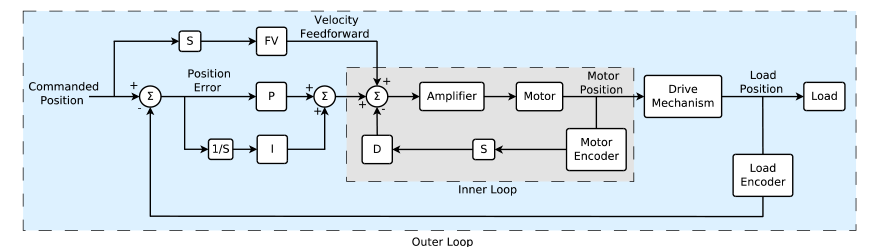
Image credit: Galil
The servo control system may also include a current control loop, positioned inside the velocity loop. Although in this scenario there would be three control loops, the term “dual-loop control” simply refers to the two control loops — position and velocity — that receive direct feedback from the encoders.
Unlike traditional cascaded control loops, in dual-loop control, the velocity loop response is independent of the feedback (and, therefore, the resolution) of the load encoder. Likewise, the position loop response is independent of the feedback from the motor encoder.
Dual-loop feedback systems can use two rotary encoders or one rotary and one linear encoder. Rotary-linear combinations are most common on linear motion systems, where there is a rotary encoder (or resolver) located on the motor and a linear encoder mounted on the linear axis.
You may be wondering, “Why not just place the encoder at the load — since then it would measure the position that we’re trying to control — and do away with the motor encoder?”
Remember that because of backlash and compliance in the drivetrain, there will be times when the motor is momentarily unloaded, or essentially de-coupled from the load. If feedback is placed only on the load, with no knowledge of the motor’s position, velocity, or torque, the motor’s operation could become unstable if this de-coupling occurs at the same time the controller is sending position-correcting commands to the motor.
Leave a Reply
You must be logged in to post a comment.