• Skip to primary navigation
  • Skip to main content
  • Skip to primary sidebar
  • Skip to footer

Motion Control Tips

Automation • Motion Control • Power Transmission

  • News
    • Industry News
    • Editor Blogs
    • Video
  • Controls
    • HMIs
    • PC-Based Controllers
    • PLCs + PACs
    • Stand-Alone Controllers
    • Software
  • Drives
    • Servo Drives
    • Stepper Drives
  • Encoders
    • Absolute Encoders
    • Incremental Encoders
    • Rotary Encoders
  • Mechanical
    • Bearings
    • Brakes + Clutches
    • Belt + chain
    • Couplings
    • Gears + Gearing
    • Lubrication
    • Shock + Vibration Mitigation
    • Springs + Rings + Seals
  • Linear
    • Actuators
    • Linear Motors
    • Linear Encoders
  • Motors
    • AC Motors
    • DC Motors
    • Brushless Motors
    • Gearmotors
    • Piezo Motors
    • Servo Motors
    • Stepper Motors
  • Systems
    • Conveyors + linear transport systems
    • Gantries + Stages
    • Rotary Tables
    • Grippers + End Effectors
    • Robotics
  • Networks
    • Connections + Sliprings
    • Fieldbuses
    • I/O
    • Sensors + Vision
  • FAQs
    • Motion Casebook
    • Motion Selection Guides
  • Suppliers
You are here: Home / FAQs + basics / Motion system design: Can a servo-driven machine be too stiff?

Motion system design: Can a servo-driven machine be too stiff?

December 23, 2019 By Danielle Collins Leave a Comment

When we think of stiffness, we often think of mechanical stiffness — the ability of a part or system to resist deflection. But in servo-driven motion systems, stiffness can also refer to how the system is tuned — that is, how the gains in the servo controller are set and, correspondingly, how the motor responds to external disturbances.


Mechanical stiffness

Systems that are mechanically stiff resist deformation when subjected to loads. In other words, they can withstand high forces or bending moments without a change in their shape or position. (Note that the opposite of mechanical stiffness is compliance.) The mechanical stiffness of a part depends on both its modulus of elasticity and its planar moment of inertia, which is determined by the size and shape of the object.

servo stiffness
The mechanical stiffness of a structure depends on its size, shape, and material.
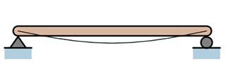
Image credit: wikipedia.org

In motion systems — such as automation or assembly equipment — the most significant influences on mechanical stiffness come from connection points between the motor and the load, including gearboxes, drive mechanisms (belt and pulley, screw, etc.), and couplings. This is one of the reasons direct drives (linear motors and torque motors) exhibit high stiffness — because the load is coupled directly to the motor, eliminating any intermediate power transmission components.

In theory, a motion system cannot be too stiff mechanically. A system with low compliance and high stiffness transmits power more efficiently and with better responsiveness than a system with low stiffness. But in real-world applications, mechanical stiffness must be balanced with damping elements to avoid transmitting shock loads and vibrations throughout the system.


Servo stiffness

In servo system tuning, stiffness — often referred to as “servo stiffness” or “control stiffness” — refers to the system’s ability to reject or overcome external disturbances. These can be disturbances that happen in a static state, when the axis is holding a position or speed, or in a dynamic state, when the axis is following a position or speed trajectory.

Servo stiffness is determined by the gains in the control loop. In motion control systems, it’s the position loop’s proportional gain that has the greatest influence on servo stiffness. Recall that the value of the proportional gain is directly proportional to the error being corrected and determines the amount of restoring force the motor will generate to counter disturbances.

An axis with proportional gain that is set too low cannot overcome disturbances (this is sometimes referred to as “softness” in the system), but if the proportional gain is too high, the system will tend to overshoot and oscillate around the target, causing instability.


If a velocity control loop is included, the velocity loop’s integral gain (Ki) also influences the servo stiffness.

Feedback Gains
Servo stiffness is primarily determined by the position loop’s proportional gain (Kp). However, if a velocity loop is included in the control, the velocity loop’s integral gain (Ki) can also influence stiffness.
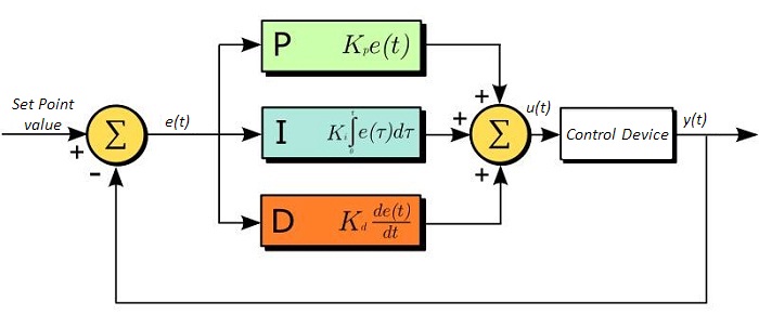
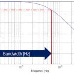
Image credit: Thorlabs, Inc.

The relationship between mechanical stiffness and servo stiffness is resonance. Systems that are mechanically stiff tend to have a high resonant frequency compared to the frequency (bandwidth) at which the servo system operates. Therefore, mechanical systems with high stiffness can benefit from stiff servo tuning (high gains) — with good response, low oscillation, and fast setting time.

On the other hand, compliant mechanical systems (those with low stiffness) operate at a lower resonant frequency. If a mechanically compliant system is operated with high servo gains (high bandwidth), the servo bandwidth could approach or overlap the mechanical resonant frequency and cause the system to become unstable.

You may also like:

  • controller
    What really limits gains in a servo system?
  • overshoot
    How to address overshoot in servo control
  • Notch Filters
    How notch filters and low-pass filters reduce resonance in servo…
  • bandwidth
    Why is the bandwidth of a servo control loop important?

  • Effects of PID and machine parameters on positioning-system performance

Filed Under: FAQs + basics, Featured, Servo Drives, Servo Motors

Reader Interactions

Leave a Reply Cancel reply

You must be logged in to post a comment.

Primary Sidebar

MOTION DESIGN GUIDES

“motion

“motion

“motion

“motion

“motion

POWER TRANSMISSION REFERENCE GUIDE

RSS Linear Motion Tips

  • Haydon Kerk Pittman launches compact Z-Theta motion platform
  • Three easy ways to specify application requirements for linear motion systems
  • Sourcing linear motion solutions from NSK’s global manufacturing sites
  • Ride the wave of electrification: Off-highway designs with linear actuators
  • What are capacitive sensors and where are they used?
Subscribe Today

RSS Featured White Papers

  • Identifying Best-Value Linear Motion Technologies
  • Learn how to reduce noise and distortion in encoders’ signals
  • Helical Planetary Gearboxes: Understanding The Tradeoffs
Tweets from https://twitter.com/Motion_Control/lists/motion-control-tweets

Footer

Motion Control Tips

DESIGN WORLD NETWORK

Design World Online
The Robot Report
Coupling Tips
Linear Motion Tips
Bearing Tips
Fastener Engineering

MOTION CONTROL TIPS

Subscribe to our newsletter
Advertise with us
Contact us
About us
Follow us on TwitterAdd us on FacebookAdd us on LinkedInAdd us on YouTubeAdd us on Instagram

Copyright © 2021 · WTWH Media LLC and its licensors. All rights reserved.
The material on this site may not be reproduced, distributed, transmitted, cached or otherwise used, except with the prior written permission of WTWH Media.

Privacy Policy | RSS