Direct drive linear servo motors have seen a measurable increase in adoption over the past several years, thanks in part to end users’ demands for higher throughput and better precision. And although linear motors are most often recognized for their ability to provide a combination of high speeds, long strokes, and excellent positioning accuracy that isn’t possible with other drive mechanisms, they can also achieve extremely slow, smooth, and precise motion. In fact, linear motor technology provides such a wide range of capabilities — thrust force, velocity, acceleration, positioning accuracy, and repeatability — that there are few applications for which linear motors are not a suitable solution.
Linear motor variations include linear servo motors, linear stepper motors, linear induction motors, and thrust tube linear motors. When a linear servo motor is the best option for an application, here are three things to consider during the initial motor selection.
The “primary” consideration: Iron core or ironless?
Linear direct drive servo motors come in two main types, iron core or ironless, referring to whether the windings in the primary part (analogous to the stator in a rotary motor) are mounted in an iron lamination stack or in epoxy. Deciding whether the application requires an iron core or an ironless linear motor is typically the first step in design and selection.
Iron core linear motors are best suited for applications that require extremely high thrust forces. This is because the lamination of the primary part contains teeth (protrusions) that focus the electromagnetic flux toward the magnets of the secondary part (analogous to the rotor in a rotary motor). This magnetic attraction between the iron in the primary part and the permanent magnets in the secondary part allows the motor to deliver high forces.
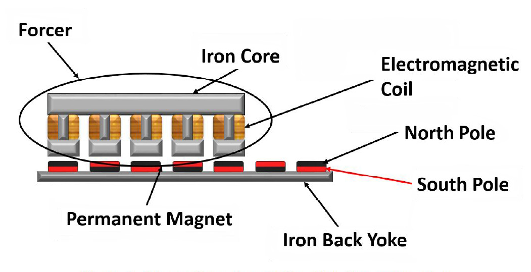
Image credit: Nippon Pulse America, Inc.
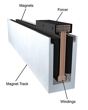
Image credit: Aerotech Inc.
Ironless linear motors generally have lower thrust force capabilities, so they’re not suitable for the extremely high thrust requirements found in applications such as pressing, machining, or molding. But they excel at high-speed assembly and transport.
Ironless linear motors are sometimes referred to as “U-channel” or “air core” linear motors because their secondary part is often shaped like a “U,” with two magnet plates facing each other, separated by a spacer. The primary part (also referred to as a “forcer”) rides in the slot, or air gap, between the two magnet plates.
The downside of the iron core design is cogging, which degrades the smoothness of motion. Cogging occurs because the slotted design of the primary part causes it to have “preferred” positions as it travels along the magnets of the secondary part. To overcome the primary’s tendency to align with the magnets of the secondary, the motor has to produce more force, which causes a velocity ripple — referred to as cogging. This variation of force and velocity ripple degrades the smoothness of motion, which can be a significant issue in applications where the quality of motion during travel (not just final positioning accuracy) is important.
There are numerous methods that manufacturers use to reduce cogging. One common approach is to skew the position of the magnets (or the teeth), creating smoother transitions as the primary teeth travel across the secondary magnets. A similar effect can be achieved by changing the shape of the magnets to an elongated octagon.

Image credit: Parker Hannifin
Another method to reduce cogging is referred to as fractional winding. In this design, the primary contains more lamination teeth than there are magnets in the secondary, and the lamination stack has a special shape. Together, these two modifications work to cancel cogging forces. And of course, software always offers a solution. Anti-cogging algorithms allow servo drives and controllers to adjust the current supplied to the primary so that variations in force and velocity are minimized.
Ironless linear motors don’t experience cogging, since their primary coils are encapsulated in epoxy, rather than being wound around a steel lamination. And ironless linear servo motors have a lower mass (epoxy is lighter, albeit less stiff, than steel), allowing them to achieve some of the highest acceleration, deceleration, and maximum velocity values found in electromechanical systems. Settling times are typically better (lower) for ironless motors than for iron core versions as well. The lack of steel in the primary, and associated lack of cogging or velocity ripple, also means ironless linear motors can provide very slow, steady motion, typically with less than 0.01 percent speed variation.
What level of integration?
Like rotary motors, linear servo motors are just one component in a motion system. A complete linear motor system also requires bearings to support and guide the load, cable management, feedback (typically a linear encoder), and a servo drive and controller. Highly experienced OEMs and machine builders, or those who have very unique design or performance requirements, can build a complete system with in-house capabilities and off-the-shelf components from various manufacturers.
Linear motor system design is arguably simpler than the design of systems based on belts, rack and pinions, or screws. There are fewer components and fewer labor-intensive assembly steps (no aligning of ball screw supports or tensioning of belts). And linear motors are non-contact, so designers don’t have to worry about making provisions for lubrication, adjustments, or other maintenance of the drive unit. But for those OEMs and machine builders who are looking for a turnkey solution, there are myriad options for complete linear motor driven actuators, high-precision stages, and even Cartesian and gantry systems.
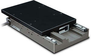
Image credit: Primatics Inc.
For the DIY-ers, choosing the appropriate linear guides for an iron core linear motor needs to be done with consideration for the attractive forces between the primary and secondary parts, which can present a significant load on the linear guides. But this isn’t a concern for ironless linear motors, since the lack of iron in the primary part means there are no attractive forces between the primary and secondary.
Is the environment suitable for a linear motor?
Linear motors are often the preferred solution in difficult environments, such as cleanrooms and vacuum environments, since they have fewer moving parts and can be paired with almost any type of linear guide or cable management to meet the particle generation, outgassing, and temperature requirements of the application. And in extreme cases, the secondary (magnet track) can be used as the moving part, with the primary part (windings, including cables and cable management) remaining stationary.
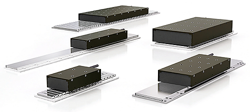
Image credit: Chieftek Precision USA
But if the environment will consist of metal chips, metallic dust, or metal particles, a linear servo motor may not be the best option. This is especially true for iron core linear motors because their design is inherently open, leaving the magnet track exposed to contamination. The semi-enclosed design of ironless linear motors provides better protection, but care should be taken to ensure the slot in the secondary part is not directly exposed to sources of contamination. There are design options for enclosing both iron core and ironless linear motors, but these can reduce a motor’s ability to dissipate heat, potentially trading one problem for another.
Feature image credit: ETEL S.A.





Leave a Reply
You must be logged in to post a comment.