Servo drives — also referred to as servo amplifiers — can be classified by the type of output stage they use:
• Pulse-width-modulated (PWM) amplifier output stage or
• Linear amplifier output stage.
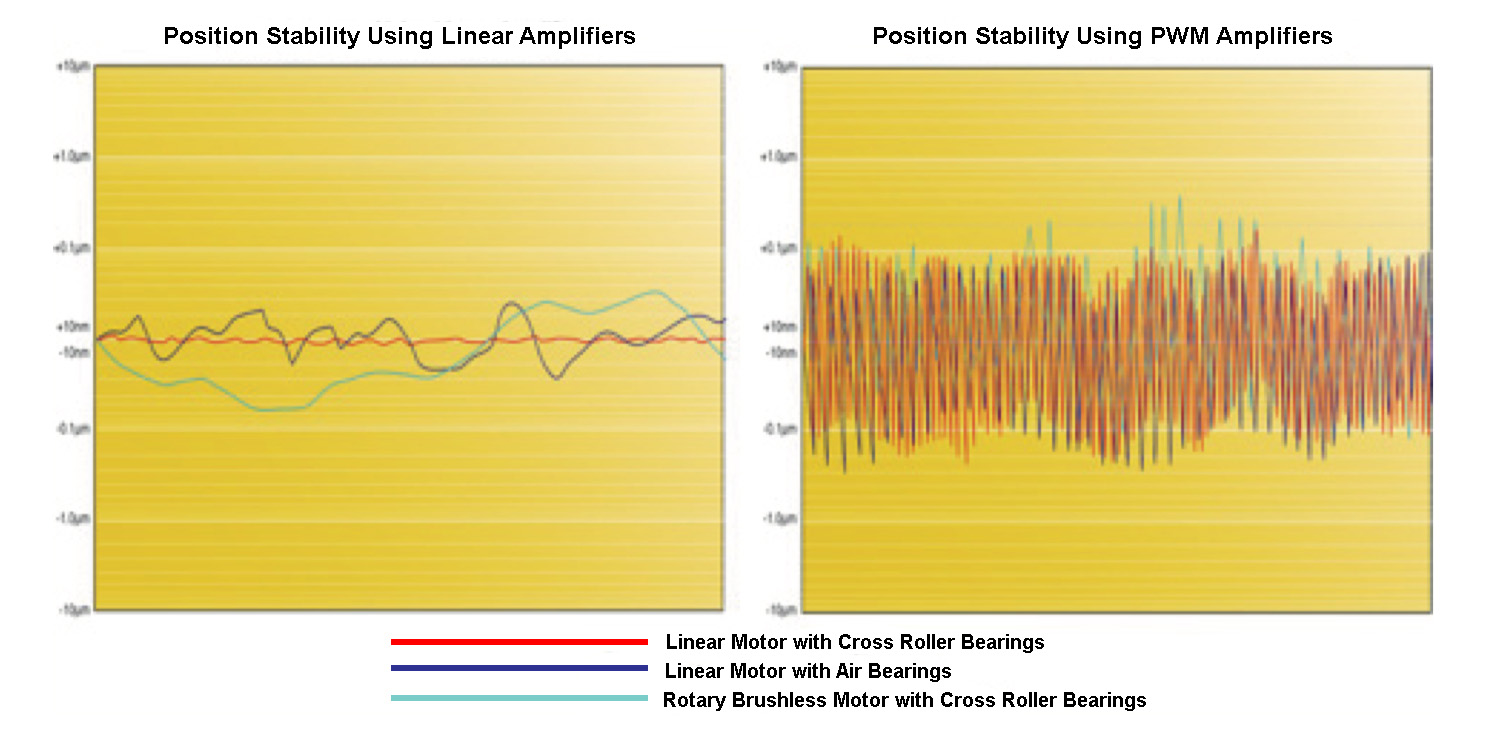
Of the two types, PWM drives are more common in general motion control applications because they provide more power to the motor, have higher efficiency, and are generally smaller and lower cost. However, while they are sufficient for most industrial applications, PWM drives create both audible noise and electromagnetic interference (EMI). They also produce minute vibrations that can interfere with sub-micron level positioning.
So for applications that require extremely smooth motion, no audible noise, and little or no EMI, linear servo drives — commonly called linear amplifiers — are preferred over PWM drives.
Note that EMI noise can interfere with other electrical equipment in the vicinity of the drive and can be especially detrimental to the operation of sensors. Although filters can be used to remove the noise, they often reduce the speed of the sensing signals.

These differences in performance are a result of the operating principles that each drive employs.
A PWM drive delivers a specified amount of voltage to the motor by switching the voltage across the transistors on and off at a very high frequency — typically in the range of 20 kHz. When the voltage is switched on, the transistors are said to be saturated. This switching creates pulses, and the switching frequency controls the width of the pulses — hence the term pulse-width modulation. The ratio of on-time to off-time during switching determines the average voltage supplied to the motor.
In contrast, in a linear amplifier, the transistors are always on to some degree. That allows voltage to flow continuously through the transistors and to the motor, rather than being switched on and off. This makes matching the amplifier’s output voltage to the motor and application requirements even more critical and, in some cases, more complex, than with PWM drives. Factors such as the motor’s torque constant, back EMF, and resistance all play a role in determining the required output voltage from a linear amplifier.
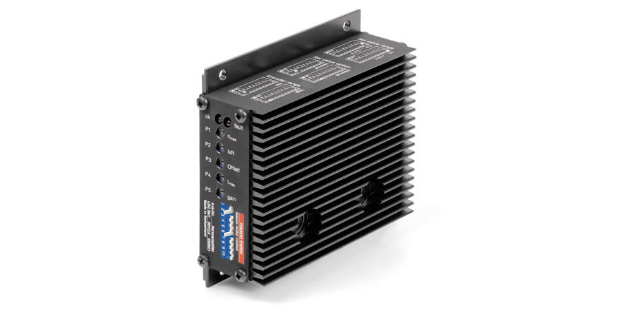
Because there is always some voltage flowing through the transistors, linear amplifiers experience significant power dissipation, and in turn, relatively low efficiency — typically in the range of 50% … although it can be lower. (In contrast, PWM drives often have efficiencies of 90% or better.) Of course, the power is dissipated as heat, which means a linear amplifier needs a large heat sink to protect the transistors, increasing size and cost and often restricting their practical applications to those with power requirements of 100 W or less.
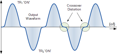
Despite these drawbacks, the lack of power switching gives linear amplifiers the benefit of very low audible noise and virtually no EMI. They also have a higher current loop bandwidth, and no dead band at the zero current crossing.

Drives that exhibit a dead band — as PWM drives do — cannot accurately provide the low levels of current required as the motor switches from positive to negative torque (or velocity) — i.e., at the “zero crossing” of the current waveform. This makes it difficult to control very small movements, which can cause dithering and long settling times. Unlike PWM drives, linear amplifiers don’t experience a dead-band, which allows them to provide much better velocity control and settling characteristics.


High current loop bandwidth, low EMI, and smooth motion characteristics make linear amplifiers the best choice for ultra-high positioning applications. They’re often used in precision stages to drive linear motors or voice coil actuators in semiconductor, medical, and optical equipment.
One final note on terminology: The term “linear” amplifier has nothing to do with whether the motor being driven is a linear or rotary version. Linear amplifiers can be used on both linear and rotary motors — either brushed or brushless. 


Leave a Reply
You must be logged in to post a comment.