
Integrated motors, sometimes called smart motors, are motors that integrate one or more motion system components. The motor part of the integrated motor can be a brushless dc motor, servomotor, or stepper motor.
Typical motion systems have a number of common components including the motor, controller, a drive and power for drive and control electronics, cabling, and feedback devices such as encoders. As a result, what constitutes an integrated motor can vary. For instance, the most basic type may consist of a motor and encoder or a motor and a drive and controller along with communication ports.
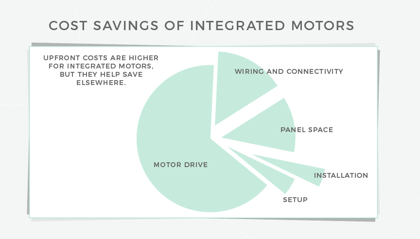
Integrated motors can boost reliability mainly because there are fewer parts to connect together. Fewer external connections means less cabling and wiring — and that minimizes costs, along with avoiding separate components purchases … as the motion controller and the drive are in one physical unit.
Integrated motors are also relatively easy to program, which can help reduce development times. Communication options range from simple serial communication links such as RS232 or RS485 to more advanced network topologies suited to complex motion control tasks such as CANopen, DeviceNet, or Ethernet protocols.
In some designs, integrated motors can also eliminate external controllers such as PLCs. Such integrated systems can reduce space needed for a machine by consolidating components— even eliminating enclosures in some cases.
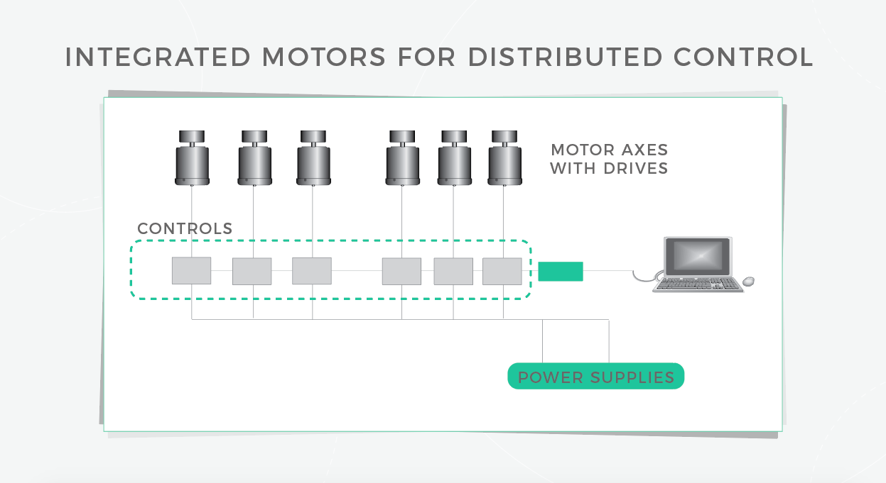
Integrated motors rose with the spread of decentralized motion control architectures. This alternative to centralized motion control distributes machine smarts to run right on motion axes (including the form of integrated motors) sometimes letting OEMs or plant engineers do away with a central controller. So motors can execute the control closer to the actual axis of motion or load, thereby taking the computational burden off of a central controller and distributing it to individual integrated motors.
When selecting an integrated motor for an application, first define load characteristics. Properly calculate load torque. Keep actual operating conditions below the published motor limits to get long and reliable operation.
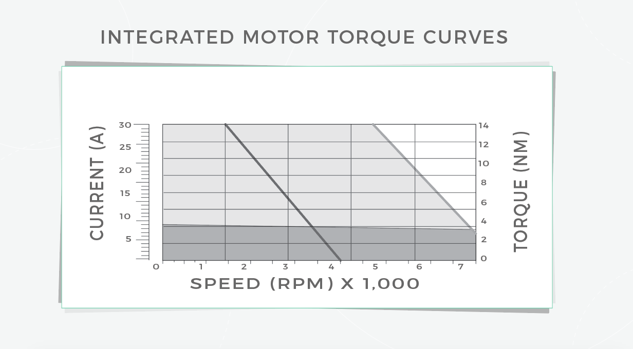
Motor sizing parameters come from torque curves and the load’s moment of inertia. These factors dictate motor operating bandwidth. Sets of torque curves depict limits of both continuous and peak torque for the given motor over its full range speed.
Different manufacturers’ torque curves present peak torques and continuous torques based on slightly different operating conditions. Peak torque curves can be derived from dyno testing and represent the point at which the drive’s hardware settings should limit peak current to prevent further torque — and protect drive stage components.
Optimized mechanical systems run off motors operating in their best ranges. One caveat here: Depending on application specifics, the design engineer may need to optimize other mechanical features (including those related to gear reducers, belts, lead screws, and pinion gears) to get the best possible design performance. For more videos like this, visit designworldonline.com and click on videos.
Leave a Reply
You must be logged in to post a comment.