
Rotary actuators — and their counterparts, rotary stages and rotary indexing tables — are designed to move loads radially with high positioning accuracy. Similar to linear actuators, sizing a rotary actuator requires evaluating parameters such as torque, speed, and inertia, as well as ensuring the actuator can meet the application requirements for positioning the load, such as repeatability and concentricity.
While the sizing process will vary slightly for different actuator configurations — mechanical drivetrain versus direct drive, servo versus stepper driven — there are some key parameters to consider when sizing and selecting any type of rotary actuator, stage, or indexing table.
Inertia
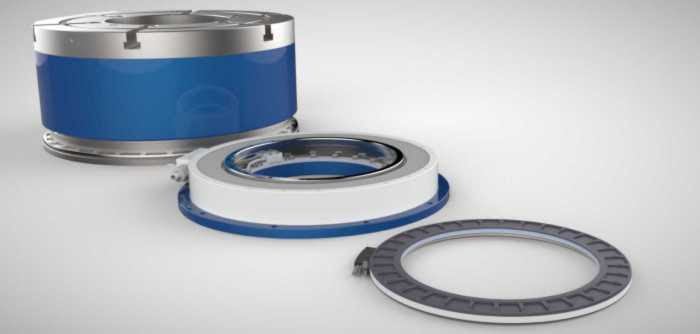
Rotary actuator sizing generally begins with determining the load inertia — a function of the load’s mass, geometry, and any gear reduction applied between the motor and actuator. The load inertia must be within the selected actuator’s “allowable load inertia” — a parameter included in the technical specifications of most rotary actuators — otherwise, the motor may not be able to effectively move and control the load. This is especially important for highly dynamic applications that involve quick acceleration and deceleration rates or frequent changes in rotational direction.
Image credit: IAI
Torque, speed, and acceleration
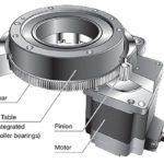
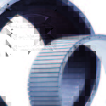
Just as a linear actuator requires force to drive a load, a rotary actuator must produce sufficient torque to move the attached load during both the constant velocity and the acceleration phases of the motion profile. For rotary actuators, speed and acceleration are typically given in radians or degrees per unit time (rad/min or deg/s, for example). Because many rotary actuators are based on direct-drive torque motors or pancake motors, or have a separate servo or stepper motor integrated, their technical specifications often include torque-speed curves, although in some cases, the bearing or encoder may limit the maximum rotational speed of the actuator.
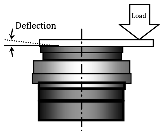
Image credit: Harmonic Drive
Some rotary actuator manufacturers also include specifications for moment stiffness and torsional stiffness. Moment stiffness — typically given in units Nm/rad — indicates the output flange’s ability to resist tilting when a load is applied at some radial distance from the center of the actuator.
Torsional stiffness indicates the tendency of table to rotate when a load is applied while the actuator is in a “locked” position. Torsional stiffness is important when the load needs to be held at a precise location, such as during inspection or machining operations.
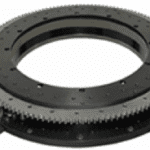
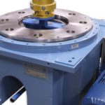
Load and bearing life
Although the attached load is a key factor in the required torque and inertia, it’s also important for determining the life of the radial bearing or crossed roller guide. When determining bearing life, both axial and radial loads should to be taken into account, as well as the combined moment load (often referred to as the tiling moment) that the radial and axial loads produce. And because rotary actuators often involve significant periods of dwell, where the load is held in a static position, static loads and moments on the bearing also need to be evaluated.
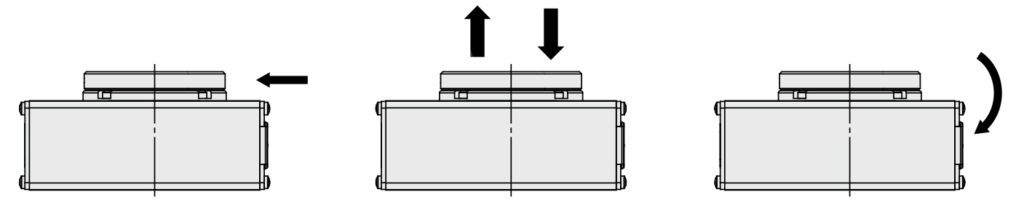
Image credit: SMC
Positioning
Along with the common specifications of positioning accuracy and repeatability, the positioning capabilities of rotary actuators are also defined by the axial and radial runout values of the output table, or flange, which are determined by the parallelism and concentricity of the output table to the base. (Runout indicates how much one surface or feature varies with respect to a datum when the actuator is rotated 360° around the datum axis.) Axial and radial runout determine how much the output flange “wobbles” — that is, how much a point on its surface varies in the vertical and horizontal directions — as it rotates.
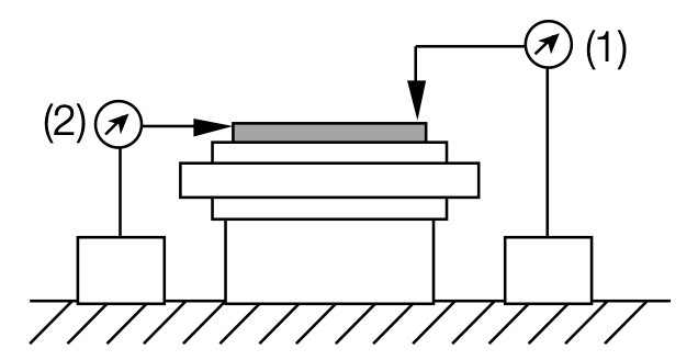
Image credit: Harmonic Drive
Leave a Reply
You must be logged in to post a comment.