
Runout is a dimensional specification that defines error in the motion of a surface as it moves relative to a datum. The official geometric dimensioning and tolerancing (GD&T) definition of runout applies to the variation of a circular feature — such as a shaft or spindle — as it rotates over 360 degrees, although the term “runout” is also sometimes used to describe error in linear motions. For rotary stages and tables, two types of runout are typically specified by manufacturers: radial runout and axial runout.
Radial runout
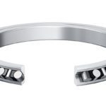
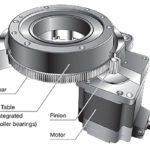
For a rotary table, radial runout can be thought of as the “roundness” of the table’s rotation. It defines the horizontal motion of the table when it rotates in a horizontal plane, and is sometimes referred to as lateral translation or eccentricity. Although various factors can contribute to radial runout, the bearings used to support the table are often the largest contributor.
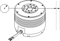
Image credit: ETEL
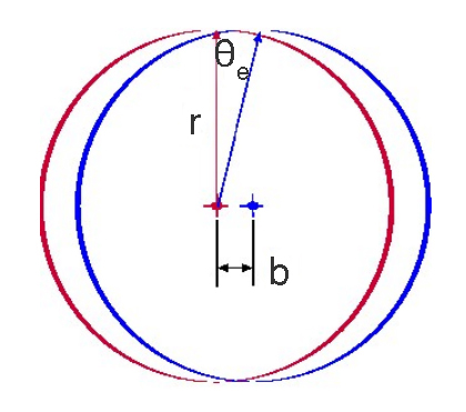
Radial runout is important because it affects the ability to center a part on the table. If radial runout is significant, a point on the surface of the part will deviate radially from its intended location and lead to unacceptable angular error, which can be calculated as follows:
![]()
θe = angular error (arcsec)
b = runout (mm)
D = diameter of the part (mm)
1.296 x 106 = conversion from degrees to arc seconds
Axial runout
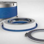
Axial runout defines the vertical motion of the surface of the table when it rotates in a horizontal plane. Axial runout affects the position of the part in the vertical direction. This is important because if the surface of the part deviates in the vertical direction, any application where the surface is a target — such as metrology, inspection, dispensing, or assembly — can be jeopardized.
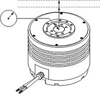
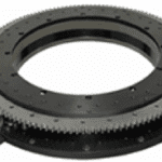
Image credit: ETEL
What is T.I.R.?
Manufacturers often specify runout values as T.I.R., which generally stands for “total indicator reading” or “total indicator runout.” Although frequently used, the term “T.I.R.” is not governed by ASME or ISO standards for GD&T, and so it can have several meanings.
However, T.I.R. is typically used in place of the term “total runout,” which ASME and ISO define as the difference between the maximum and minimum values measured across the entire rotating surface (rather than at a single point on the surface).
The symbol for total runout is a double arrow, while the symbol for runout is a single arrow. If the specification of T.I.R. is used in combination with the double arrow symbol, this indicates that the specification is being given in accordance with the ASME/ISO definition of total runout.
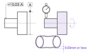
Image credit: Keyence Corporation
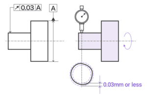
Image credit: Keyence Corporation
This article from Manufacturing Technology, Inc. does an excellent job of explaining the difference between total runout (which they refer to as T.I.R.) and runout.
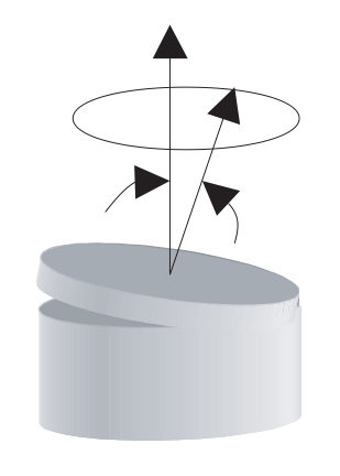
Image credit: Parker
Wobble
In addition to radial and axial runout, some manufacturers also specify “wobble,” or tilt error motion. Unlike runout, which is the deviation of a surface, wobble is the deviation of the axis of rotation relative to the ideal axis, and is given in angular units (arc seconds or microradians, for example)
To picture wobble, imagine a surface (such as the mounting surface of the rotary table) rotating between two parallel planes. Wobble is the amount by which the rotating surface deviates from parallel with the upper and lower planes.
Leave a Reply
You must be logged in to post a comment.