• Skip to primary navigation
  • Skip to main content
  • Skip to primary sidebar
  • Skip to footer

Motion Control Tips

Automation • Motion Control • Power Transmission

  • News
    • Industry News
    • Editor Blogs
    • Video
  • Controls
    • HMIs
    • PC-Based Controllers
    • PLCs + PACs
    • Stand-Alone Controllers
    • Software
  • Drives
    • Servo Drives
    • Stepper Drives
  • Encoders
    • Absolute Encoders
    • Incremental Encoders
    • Rotary Encoders
  • Mechanical
    • Bearings
    • Brakes + Clutches
    • Belt + chain
    • Couplings
    • Gears + Gearing
    • Lubrication
    • Shock + Vibration Mitigation
    • Springs + Rings + Seals
  • Linear
    • Actuators
    • Linear Motors
    • Linear Encoders
  • Motors
    • AC Motors
    • DC Motors
    • Brushless Motors
    • Gearmotors
    • Piezo Motors
    • Servo Motors
    • Stepper Motors
  • Systems
    • Conveyors + linear transport systems
    • Gantries + Stages
    • Rotary Tables
    • Grippers + End Effectors
    • Robotics
  • Networks
    • Connections + Sliprings
    • Fieldbuses
    • I/O
    • Sensors + Vision
  • FAQs
    • Motion Casebook
    • Motion Selection Guides
  • Suppliers
You are here: Home / FAQs + basics / FAQ: Why are DC motor armature cores made of laminations?

FAQ: Why are DC motor armature cores made of laminations?

December 18, 2016 By Danielle Collins Leave a Comment

DC motors are constructed with two major parts: the rotor and the stator. The rotor has a ring-shaped iron core with slots that hold coils, or windings. Following Farady’s law, when the core is rotated in a magnetic field, a voltage, or EMF, is induced in the coils. This induced EMF causes current to flow, known as eddy current.

laminations
Eddy currents are the result of the armature core rotating in a magnetic field.
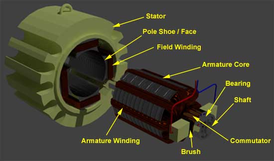
Image credit: electrical4u.com

Eddy currents are a form of magnetic loss, and the power loss due to the flow of eddy currents is referred to as eddy current loss. (Hysteresis loss is another component of magnetic loss.) These losses produce heat and reduce motor efficiency.


The amount of eddy current loss depends on several factors, including:

  • the magnetic flux density
  • the frequency of the induced EMF (the frequency at which the polarity of flux changes)
  • the thickness of the magnetic material

Pe = Ke * B2 * f2 * t2

Where:

Pe = eddy current loss

Ke = eddy current constant

B = flux density

f = frequency of magnetic reversals

t = material thickness


The development of eddy currents is influenced by the resistance of the material in which they flow. For any magnetic material, there is an inverse relationship between the material’s cross-sectional area and its resistance, meaning that a reduction in area causes an increase in resistance, and in turn, a decrease in eddy currents. One way to achieve a reduction in cross-sectional area is to make the material thinner.

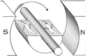
This is why armature cores are made up of many thin pieces of iron, rather than a large, solid piece. These individual, thin pieces have a higher resistance than one solid piece, and therefore, produce less eddy currents and experience lower eddy current loss.

The individual iron pieces that make up the armature are referred to as laminations.

laminations
The top image depicts a solid armature, while the bottom image shows an armature made of five laminations. The sum of the eddy currents in the laminated core is smaller than the current in the solid core.
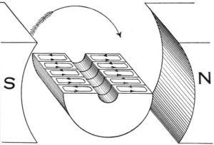
Image credit: wikipedia.org

These laminations are insulated from each other, typically by a lacquer coating, to prevent the eddy currents from “jumping” from lamination to lamination. The inverse-square relationship between material thickness and eddy current loss means that any reduction in thickness will have a significant effect on the amount of loss. Because of this, manufacturers strive to make armature core laminations as thin as practical from a manufacturing and cost standpoint, with modern DC motors typically using laminations that are 0.1 to 0.5 mm thick.

Feature image credit: brighthubengineering.com

You may also like:

  • DC shunt motors
    FAQ: What are rotational losses in DC motors?

  • Lenz’s Law and Back EMF
  • motor terminology
    FAQ: What are the different ways that industry classifies servo…
  • Commutator
    What is a commutator?

  • FAQ: How to pick between stepper motor, brush dc, and…

Filed Under: DC Motors, FAQs + basics, Featured

Reader Interactions

Leave a Reply

You must be logged in to post a comment.

Primary Sidebar

POWER TRANSMISSION REFERENCE GUIDE

DESIGN GUIDE LIBRARY

“motion
Subscribe Today

RSS Featured White Papers

  • Specifying electric rodless actuators: Ten tips for maximizing actuator life and system performance
  • The truth about actuator life: Screw drive survival
  • Top Ten Tips: How to specify electric rod-style actuators for optimal performance, reliability and efficiency

Footer

Motion Control Tips

DESIGN WORLD NETWORK

Design World Online
The Robot Report
Coupling Tips
Linear Motion Tips
Bearing Tips
Fastener Engineering.

MOTION CONTROL TIPS

Subscribe to our newsletter
Advertise with us
Contact us
About us
Follow us on TwitterAdd us on FacebookAdd us on LinkedInAdd us on YouTubeAdd us on Instagram

Copyright © 2022 · WTWH Media LLC and its licensors. All rights reserved.
The material on this site may not be reproduced, distributed, transmitted, cached or otherwise used, except with the prior written permission of WTWH Media.

Privacy Policy | RSS