Starters are used to protect DC motors from damage that can be caused by very high current and torque during startup. They do this by providing external resistance to the motor, which is connected in series to the motor’s armature winding and restricts the current to an acceptable level.
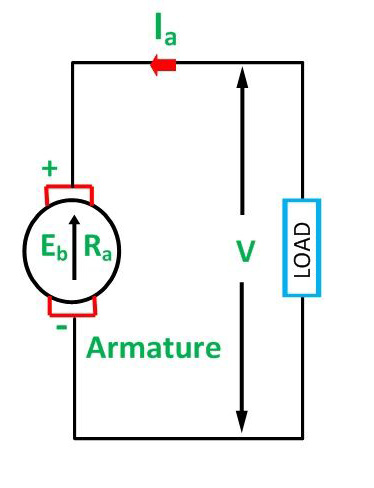
To see why DC motors experience high startup current, we can examine the voltage equation of a DC motor:
![]()
Where:
E = supply voltage
Eb = back EMF
Ia = armature current
Ra = armature resistance
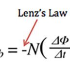
Back EMF is directly proportional to the motor’s speed, so at startup, when motor speed is zero, back EMF is also zero. Therefore, removing the Eb term and rearranging the voltage equation, we can see that, at startup, armature current is inversely proportional to armature resistance.
![]()
For the best motor performance, armature resistance in DC motors is kept very low (typically less than 1 ohm). To see how significantly this affects the starting current, we can assume that armature resistance (Ra) is 0.4 ohm and supply voltage (E) is 220 V. This gives a starting current (Ia) of 550 amps, which can be more than ten times the rated current, and high enough to damage the internal motor circuit.
Not only can the high startup current result in potential motor circuit damage, it can also produce dangerously high torque, which can cause the rotor to literally break apart. From the DC motor torque equation, we can see that torque is directly proportional to current:
![]()
Where:
T = torque
ka = torque constant
φ = motor flux
To combat these problems, a motor starter adds external resistance (Rs) to the armature winding, which reduces the armature current:
![]()
But this resistance doesn’t need to be present through the motor’s full operating speed range. As motor speed increases, back EMF develops, which counters the supply voltage and also has the effect of reducing armature current:
![]()
As the back EMF reaches its maximum, the starter progressively decreases the external resistance, Rs, to zero.
Types of DC motor starters
Shunt wound and compound wound DC motors typically use either a 3 point or 4 point starter. The name comes from the number of terminals that connect to the motor, with 3 point starters having three terminals: the armature terminal, which is connected to the motor armature winding; the line terminal, which is connected to the positive supply pole; and the field terminal, which is connected to the field winding.
Four point starters are virtually identical to 3 point starters, but they have an additional terminal, labeled the “N” terminal, which links the supply to the no voltage coil of the starter. This protects against unnecessary tripping when the motor is run above its normal speed. Series wound motors typically use 4 point starters.
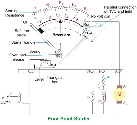
Image credit: electrical4u.com
Three point and 4 point starters are manually controlled by an operator, who adjusts the resistance that’s delivered to the motor through a simple lever or handle. But electronic starters are also available, using a micro controller and thyristors to regulate the resistance delivered to the motor. A more recent development are starters that use “voltage chopping,” rather than resistance, to limit the startup current. “Chopping” the frequency of the input voltage varies its ratio of on-time versus off-time. This allows the average voltage to be controlled, so that armature current is kept to an acceptable level while speed (and, thus, back EMF) is developed.
Feature image credit: ABB


Leave a Reply
You must be logged in to post a comment.