• Skip to primary navigation
  • Skip to main content
  • Skip to primary sidebar
  • Skip to footer

Motion Control Tips

Automation • Motion Control • Power Transmission

  • News
    • Industry News
    • Editor Blogs
    • Video
  • Controls
    • HMIs
    • PC-Based Controllers
    • PLCs + PACs
    • Stand-Alone Controllers
    • Software
  • Drives
    • Servo Drives
    • Stepper Drives
  • Encoders
    • Absolute Encoders
    • Incremental Encoders
    • Rotary Encoders
  • Mechanical
    • Bearings
    • Brakes + Clutches
    • Belt + chain
    • Couplings
    • Gears + Gearing
    • Lubrication
    • Shock + Vibration Mitigation
    • Springs + Rings + Seals
  • Linear
    • Actuators
    • Linear Motors
    • Linear Encoders
  • Motors
    • AC Motors
    • DC Motors
    • Brushless Motors
    • Gearmotors
    • Piezo Motors
    • Servo Motors
    • Stepper Motors
  • Systems
    • Conveyors + linear transport systems
    • Gantries + Stages
    • Rotary Tables
    • Grippers + End Effectors
    • Robotics
  • Networks
    • Connections + Sliprings
    • Fieldbuses
    • I/O
    • Sensors + Vision
  • FAQs
    • Motion Casebook
    • Motion Selection Guides
  • Suppliers
You are here: Home / FAQs + basics / Moments of inertia: Definitions and equations

Moments of inertia: Definitions and equations

April 6, 2018 By Danielle Collins Leave a Comment

The term “moment of inertia” is often used generically, but depending on the context and application, it can refer to one of three different moments of inertia: mass, planar, or polar. In order to know which one is needed for a given calculation or analysis, it’s important to understand the differences between them and how each one relates to the behavior of an object.


Mass moment of inertia formula

Mass moment of inertia describes the object’s ability to resist angular acceleration, which depends on how the object’s mass is distributed with respect to the axis of rotation (i.e., the object’s shape). Mass moment of inertia is typically denoted as “I,” although “J” is commonly used in engineering references, such as motor or gearbox inertia specifications. Its units are mass-distance squared: kgm2 or lbm-ft2. (Note that slug-ft2 is also sometimes used.)

moments of inertia
Image credit: brilliant.org

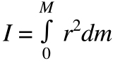
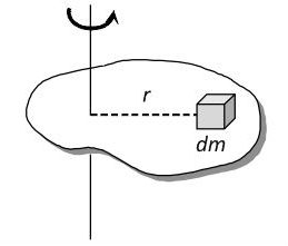
In many applications, an object is modeled as a point mass, and the mass moment of inertia is simply the object’s mass multiplied by the radius (distance to axis of rotation) squared.

moments of inertia

moments of inertia
Image credit: brilliant.org

Mass moment of inertia is important for motor sizing, where the inertia ratio — the ratio of the load inertia to the motor inertia — plays a significant role in determining how well the motor can control the load’s acceleration and deceleration.

Planar and polar moments of inertia formulas

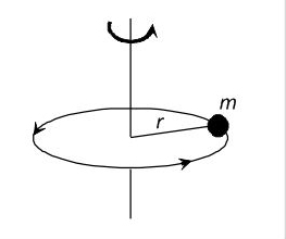
Planar and polar moments of inertia both fall under the classification of “second moment of area.” Planar moment of inertia describes how an area is distributed relative to a reference axis (typically the centroidal, or central, axis). This is important because it specifies the area’s resistance to bending.

The equation for planar moment of inertia takes the second integral of the distance to the reference plane, multiplied by the differential element of area. The result is expressed in units of length to the fourth power: m4 or in4.

moments of inertia

moments of inertia
Image credit: arizona.edu

Polar moment of inertia is analogous to planar moment of inertia but is applicable to a cylindrical object and describes its resistance to torsion (twisting due to an applied torque).

The equation for polar moment of inertia is essentially the same as that for planar moment of inertia, but in the case of polar moment, distance is measured to an axis parallel to the area’s cross-section. Polar moment of inertia is sometimes denoted with the letter J, instead of I, but its units are the same as those for planar moment of inertia: m4 or in4.

moments of inertia

Polar moment of inertia (denoted here as Ip) can also be found by summing the x and y planar moments of inertia (Ix and Iy).

moments of inertia

moments of inertia

Planar and polar moments of inertia are used when calculating deflection — either linear displacement due to an applied force or angular displacement due to an applied moment.

You may also like:

  • gear ratio
    How do I determine what gear ratio I need for…

  • 9 considerations when picking servocouplings for servo applications — and…

  • Sizing and selecting servos: The need for a system approach
  • Linear motion
    7 linear motion principles that electrical engineers should know
  • inertia ratio
    FAQ: How do I calculate the inertia of a servo-driven…

Filed Under: FAQs + basics, Featured

Reader Interactions

Leave a Reply

You must be logged in to post a comment.

Primary Sidebar

POWER TRANSMISSION REFERENCE GUIDE

DESIGN GUIDE LIBRARY

“motion
Subscribe Today

RSS Featured White Papers

  • Specifying electric rodless actuators: Ten tips for maximizing actuator life and system performance
  • The truth about actuator life: Screw drive survival
  • Top Ten Tips: How to specify electric rod-style actuators for optimal performance, reliability and efficiency

Footer

Motion Control Tips

DESIGN WORLD NETWORK

Design World Online
The Robot Report
Coupling Tips
Linear Motion Tips
Bearing Tips
Fastener Engineering.

MOTION CONTROL TIPS

Subscribe to our newsletter
Advertise with us
Contact us
About us
Follow us on TwitterAdd us on FacebookAdd us on LinkedInAdd us on YouTubeAdd us on Instagram

Copyright © 2022 · WTWH Media LLC and its licensors. All rights reserved.
The material on this site may not be reproduced, distributed, transmitted, cached or otherwise used, except with the prior written permission of WTWH Media.

Privacy Policy | RSS