Because stepping motors are relatively inexpensive and easy to control, they’re often the first option to consider in machine designs. Low-cost solutions have had performance limitations, but new control technology substantially enhances stepping motors capability.
Stepping motors have progressed over the years from the early days of the world’s first digital motor into a broad based solution that is increasingly common for several good reasons. One reason is ease of use. Stepping motors are designed to be controlled using two TTL switches, one for the step itself and the other for the direction of motion. It doesn’t get any easier than that. In the age of digital controls, this is an ideal way to manage moving a load. Digital pulses can be programmed with ultimate precision and translated through MOSFET power switches to deliver torque, speed and position at the output shaft of the motor.
While stepping motors exist with several different step geometries, the most common stepping motor is designed to be 200 steps per rotation. When combined with a 5:1 pitch lead screw, every step of the motor produces one thousandth of an inch of linear travel. This makes programming motion profiles, especially Cartesian coordinates, straightforward. Cartesian motion can be thought of as Tic-Tac-Toe types of motion versus drawing a circle or more complex moves, such as would be found in a CNC machine.
Part of the low cost of implementing stepping motors is the ability to operate without feedback. A properly sized stepping motor application does not require an encoder to close the position loop of the controller. Stepping motor controls are also relatively simple and inexpensive.
Limitations of traditional stepping motors
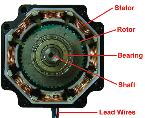
Stepping motors take steps instead of rotating freely like a conventional motor in part because there are “teeth” in the rotor and stator, easily seen in the cross section of a standard stepping motor. This produces a local magnetic field that attracts the rotor to a relative position in the circumference of the stator. This mechanical arrangement combined with the switching of electromagnetic fields in the stator is what creates the step.
Unfortunately, the magnetic force acts like a spring causing the rotor to “ring” or oscillate slightly as it settles into position. In high-speed systems, the settling time is wasted time waiting for the motor to stop vibrating and this wait time can limit production speed. In addition to the settling time issues, a springy actuator can be subject to other issues based on frequency. If a natural frequency in the combined rotor and load is excited by a certain operating speed that the stepping motor is running at, it can produce an unstable condition and the motor will lose position. A variety of countermeasures have been created to circumvent this behavior. Everything from adding inertia mass, frequency filters, electronic damping and even the addition of an external encoder can be used to minimize frequency related problems.
Microstepping systems were created to increase the resolution of the motor without the need for a complete redesign of the mechanics of the motor. Because a stepping motor is a two-phase electrical machine, it’s possible to control the current in each phase and gradually position the motor between the teeth of the motor’s construction, hence the term micro step. This approach to controlling the motor works quite well and has been an industry standard for improved smoothness and resolution.
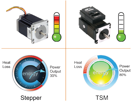
Most stepping motors run very hot because the power going through the motor and power electronics are not well regulated. Some controllers have reduced current settings to provide a holding torque when the motor is not moving to minimize this, but the ideal power regulation scheme has not been found.
Notwithstanding some of the quirks of the technology, there are millions of stepping motor driven pan and tilt camera mounts that work perfectly. There are even more printers using stepping motors to advance the paper and position the print head. But the history of the motor industry has been that there is always demand for greater performance.
A new solution
What would happen if closed loop current regulation could be added to the stepping motor just like in a brushless servo? As it turns out, the new Step Servo control from Applied Motion Products does exactly that.
Using closed-loop current regulation means that the motor only receives as much energy as is needed to regulate the load. If the load isn’t moving, there is almost no power going to the motor. If the load is deflected out of position by even one encoder count, the drive pushes the motor back into position. Heating in the motor and the drive circuit are eliminated in most applications. Normally an integrated motor and controller requires some level of de-rating to manage the heat generated, but with the new technology this compromise is largely eliminated.
In addition, the current regulation imparts a smoothness that is just like micro-stepping. This is because the current in each phase is switched on and off gradually, rather than through a square wave “thump” of power. The smooth sinusoidal current ramp and timing in each phase provides an electronic means of smoothing the detent in the stepping motor that is present based on its construction.
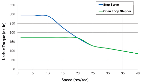
Instead of the normal de-rated starting or pull-in torque being 65 to 70% of the stepping motors rating, the Step Servo control allows the motor to produce full torque at low speed. This results in improved acceleration and increased inertia load capacity. Jeff Kordik, Applied Motion’s Chief Technology Officer, said, “In many cases with moderate duty cycles, users can apply the next smaller size of motor and drive because of the improved performance both in torque and thermal limit. The benefit in packaging of complex systems can be really significant in terms of size, weight, heat dissipation and ultimately, reduced cost.”
Improved thermal performance also makes possible a feature called Torque Boost. As the name implies, the drive electronics can provide more torque for starting and stopping as long as the overall energy through the motor averages within the continuous rating it’s designed for; 50% more torque is available for demanding acceleration and deceleration with no extra cost.
Operating an axis of motion in torque mode is generally considered the exclusive domain of the dc brush and brushless servo. This restriction has also been eliminated in the Step Servo controller. Because the current loop, or torque loop, is being closed at extremely high frequency, the stepping motor is now able to operate quite easily as a tensioning device. For the first time, complex applications involving web or wire tensioning can be managed with a stepping motor system.
Currently the Step Servo product from Applied Motion is available as a fully integrated solution in a motor/drive/feedback package. This approach eliminates the cost and complexity of discretely wiring the motor winding, feedback channels and sensors usually required with a stand-alone control. Anyone who has experienced the difficulty of trouble shooting a multi-axis control system with “ghosts in the machine” knows that minimizing discrete wire connections is a great way to improve reliability.
Integrated stepping motor solutions have been available for some time and offer the convenience of eliminating a lot of wiring. This convenience comes at the cost of reducing the torque rating of the motor and controller due to the thermal limitations. In the new Step Servo the opposite is true. Peak and continuous power ratings are achievable, depending on the duty cycle of the load, that may allow the user to change to a smaller motor and get the same work done.
Applied Motion Products
www.applied-motion.com


Leave a Reply
You must be logged in to post a comment.