• Skip to primary navigation
  • Skip to main content
  • Skip to primary sidebar
  • Skip to footer
  • Advertise
  • Subscribe

Motion Control Tips

Automation • Motion Control • Power Transmission

  • News
    • Industry News
    • Editor Blogs
  • Controls
    • HMIs
    • PC-Based Controllers
    • PLCs + PACs
    • Stand-Alone Controllers
    • Software
  • Drives
    • Servo Drives
    • Stepper Drives
  • Encoders
    • Absolute Encoders
    • Incremental Encoders
    • Rotary Encoders
  • Mechanical
    • Bearings
    • Brakes + Clutches
    • Belt + chain
    • Couplings
    • Gears + Gearing
    • Lubrication
    • Shock + Vibration Mitigation
    • Springs + Rings + Seals
  • Linear
    • Actuators
    • Linear Motors
    • Linear Encoders
  • Motors
    • AC Motors
    • DC Motors
    • Brushless Motors
    • Gearmotors
    • Piezo Motors
    • Servo Motors
    • Stepper Motors
  • Systems
    • Conveyors + linear transport systems
    • Gantries + Stages
    • Rotary Tables
    • Grippers + End Effectors
    • Robotics
  • Networks
    • Connections + Sliprings
    • Fieldbuses
    • I/O
    • Sensors + Vision
  • Resources
    • FAQs
      • Motion Casebook
      • Motion Selection Guides
    • Suppliers
    • Video
You are here: Home / FAQs + basics / What determines worm gear efficiency, and is it really that low?

What determines worm gear efficiency, and is it really that low?

December 22, 2022 By Danielle Collins Leave a Comment

Worm gears are often used for their ability to provide very high reduction ratios (and high torque multiplication) in a compact, single-stage design. But traditional thinking says that these benefits come at the expense of efficiency. Here, we’ll look at the factors that determine worm gear efficiency and how to get the benefits they provide without sacrificing efficiency.


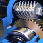
Worm gears are a type of cross-axis (non-parallel) gears, meaning they have non-intersecting shafts oriented at 90 degrees to each other. The worm, or shaft, is similar to a screw with a V-type thread, and the gear (also referred to as a worm wheel) is similar to a spur gear. The worm and gear are made of dissimilar materials, with the worm often made of steel and the gear typically made of bronze, although other material combinations can be used to suit specific loading or environmental conditions.

worm gears
Although worm gears are typically thought of as low-efficiency drives, manufacturers have made advances in materials, manufacturing methods, and lubrication options, which have led to improvements in efficiency.
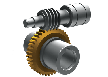
Image credit: Nord Drivesystems

Unlike other gears, which experience primarily rolling contact as teeth mesh, worm gear meshing is dominated by sliding friction between the gear teeth and the worm. This sliding friction causes significant heat generation and — generally speaking — leads to lower efficiencies than other gearbox designs. And as the reduction ratio increases, the lead angle decreases. This smaller lead angle means there’s more surface contact between the gear teeth and the worm, and, in turn, higher friction and lower efficiency.

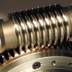
The sliding friction experienced by worm gears also causes lubrication between the meshing components to be pushed away, so the gear set operates primarily in a condition of boundary lubrication, or boundary friction. Because of these conditions, worm gears are typically lubricated with compound oils or synthetic lubricants. In addition to high viscosity, worm gear lubricants should be able to withstand high operating temperatures and pressures and be compatible with the soft metals (or, in some cases, polymers) used for the worm gear.

self-locking
As the reduction ratio increases, a worm gear’s lead angle increases, which means more contact area between the gear and the shaft, and in turn, increased friction and heat and reduced efficiency.
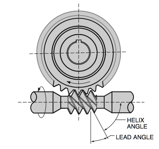
Image credit: HBD/Winsmith, Inc.

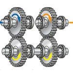
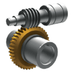
Other factors that reduce the efficiency of worm gears are friction losses due to the bearings and shaft seals. One way to mitigate these losses — especially when high gear ratios are needed — is to combine a worm gear with a helical gear. In this arrangement, the helical gear provides an initial, smaller reduction ratio, and the worm gear provides the remainder of the necessary reduction. This keeps the worm gear reduction from being so large as to result in a significant decrease in efficiency. It also provides an alternative to using a multi-stage helical gear, which would require multiple gear trains and several bearings, each of which adds friction and decreases efficiency.

worm gear efficiency
Worm gear efficiency can range from approximately 50 percent for a 300:1 ratio to around 95 percent for a 5:1 ratio.
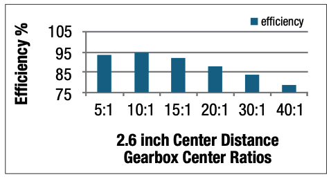
Image credit: Altra Motion

You Might Also Like

Filed Under: FAQs + basics, Featured, Gears + Gearing

Reader Interactions

Leave a Reply

You must be logged in to post a comment.

Primary Sidebar

LEARNING CENTER

Design World Learning Center

Motion Control Handbook

“mct
EXPAND YOUR KNOWLEDGE AND STAY CONNECTED
Get the latest info on technologies, tools and strategies for Design Engineering Professionals.

RSS Featured White Papers

  • Robotic Automation is Indispensable for the Logistics Industry’s Continued Growth and Success
  • Reliable Linear Motion For Packaging Machines
  • Polymers Outperform Metals In Precision Gearing

Footer

Motion Control Tips

DESIGN WORLD NETWORK

Design World Online
The Robot Report
Coupling Tips
Linear Motion Tips
Bearing Tips
Fastener Engineering.
Wire and Cable Tips

MOTION CONTROL TIPS

Subscribe to our newsletter
Advertise with us
Contact us
About us

Copyright © 2025 · WTWH Media LLC and its licensors. All rights reserved.
The material on this site may not be reproduced, distributed, transmitted, cached or otherwise used, except with the prior written permission of WTWH Media.

Privacy Policy | RSS