
Gearboxes are commonly used in motion control applications to change the output speed and torque from a motor to a driven component. By using a smaller gear with fewer teeth (commonly referred to as a pinion) to drive a larger gear with a higher number of teeth, the torque delivered to the load is increased while the rotational speed to the load is decreased.
In gearboxes using spur, helical, or bevel gears, the gear ratio — the amount of torque multiplication and speed reduction — is simply the ratio of the number of teeth on the driven (larger) gear to the number of teeth on the driving (smaller, or pinion) gear.
In theory, any gear ratio could be obtained by adjusting the number of teeth on the driving and driven gears, but in real-world operation, high gear ratios introduce design challenges — such as the need for a very small pinion (driving gear), high stresses on gear teeth, and limited torque transmission capabilities. Fortunately for machine designers, these challenges can be easily addressed with a multi-stage gearbox.
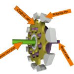
The calculation of gear ratio for a single-stage planetary gearbox depends on which gears are the driven, stationary, and output components. In most planetary gearboxes used in motion control, the sun is the driven gear, the ring gear is stationary, and the carrier drives the output shaft. For this configuration, the gear ratio (ip) is equal to one plus the ratio of ring gear teeth (Zr) to sun gear teeth (Zs), or ip = 1 + Zr/Zs.
A multi-stage gearbox simply combines two or more pairs, or stages, of gears, with the output of one stage connected to the input of the next. The resulting gear ratio is the product of the gear ratios of each stage. For example, a two-stage gearbox consisting of one stage with a 5:1 gear ratio and a second stage with a 3:1 gear ratio provides an output ratio of 15:1 (5 x 3), so the torque delivered to the load is 15 times higher the torque provided by the motor — not including transmission losses — and the speed delivered to the load is 1/15 the speed of the motor.
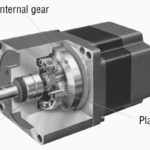
Unlike multi-stage gearboxes that consist of parallel gears, a multi-stage planetary gearbox, as shown in this video from Neugart, consists of stages that are connected concentrically, giving them a more compact footprint than parallel designs when very high reduction ratios are needed.
Multi-stage gearboxes can — and often do — consist of different types of gearing at each stage. For example, a right angle planetary gearbox can be constructed with a planetary stage and a spiral-bevel stage. And as shown in the example above, the amount of reduction for each stage can be different, but multi-stage gearboxes are typically designed with a higher gear ratio at the input and a lower ratio at the output side.
The total efficiency of a multi-stage gearbox (or a suitable estimate) can be found by multiplying the efficiencies of each stage. And it’s important to note that each stage reverses the direction of rotation between the input and output — with the exception of a planetary stage, in which the direction of rotation is maintained between the input and the output.
For most single-stage gearboxes, the directions of rotation of the input and output shafts are opposite, while for two-stage gearboxes, the additional change in direction by the second stage puts the output shaft rotation the same as the input shaft, as shown in the illustration below.
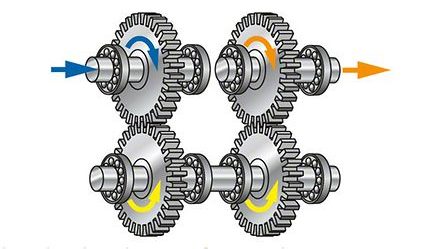
Image credit: KSB
Although efficiency is decreased to some degree, multi-stage gearboxes offer higher gear ratios than could be achieved with most single-stage gear designs. And they do so in a compact package that can be optimized to achieve the best combination of torque transfer capability, low inertia, and high efficiency.
Worm gears offer very high ratios in a single stage — up to 60:1 or greater in some cases — without the complexity of multiple gear trains, although their efficiencies tend to be lower than multi-stage designs.

Leave a Reply
You must be logged in to post a comment.