
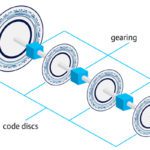
There are several ways to measure the position of a rotary axis, and some position measuring devices, such as incremental and absolute encoders, can also derive the speed of the axis by evaluating a combination of distance, time, and pulses. But for applications that require only speed measurement — without position information — a tachogenerator may be the best solution.
Recall that a generator is a device that produces electrical power from mechanical energy, with the voltage of the generated power being directly proportional to the device’s shaft speed.
Tachogenerators are true speed measuring devices that rely on the basic principle of a generator to determine the speed of a rotating part based on voltage. A tachogenerator is attached to the object whose speed is being measured — such as a fan or motor shaft — and evaluates the voltage of the power produced by the generator to determine the rotational speed of the object. Tachogenerators are designed to ensure that the relationship between voltage and speed is extremely precise and linear within a specified range.
![]()
Vo = output voltage (V)
Kt = tachogenerator constant (V-s/rad)
ωs = angular speed (rad/s)
![]()
Φ = flux per pole (Weber)
P = number of poles
Z = number of conductors in armature windings
a = number of parallel paths in armature windings
Most tachogenerators used today are brushed DC types with a permanent magnet stator and a wound, rotating armature. One end of the armature is attached to the object whose speed is being measured, and the armature rotates within the magnetic field of the stator. As the measured object rotates, the rotation of the tachogenerator armature induces a voltage, and the amplitude of the voltage is proportional to the speed of rotation. A commutator converts the alternating current generated by rotation into direct current that can be interpreted by a voltmeter circuit and converted to speed. If the direction of rotation changes, the voltage polarity changes, so DC tachogenerators can determine both speed and direction of rotation.
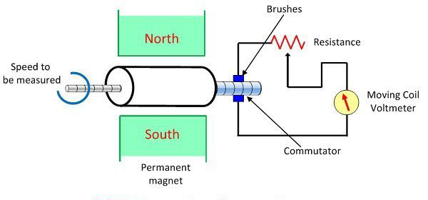
Image credit: Circuit Globe
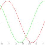
An AC tachogenerator does away with brushes and instead uses a stationary, wound stator and a rotor with permanent magnets. In this case, the rotating magnetic field of the rotor induces voltages in the 3-phase windings of the stator. The amplitude and frequency of the induced voltage are proportional to the speed of rotation. The AC output is rectified to a DC voltage whose amplitude is proportional to the speed of rotation, and the rectified output goes through a smoothing filter to reduce voltage ripples. Because AC current changes polarity twice per electrical cycle, an AC tachogenerator cannot determine the direction of shaft rotation. But because they don’t require mechanical brushes, AC versions generally exhibit longer life and lower maintenance requirements then DC tachogenerators.
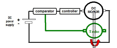
In motion control applications, tachogenerators are typically used with DC motors and drives to control motor speed.
The tachometer in your car is essentially a tachogenerator with an analog dial or digital display.
Leave a Reply
You must be logged in to post a comment.