When you hear the term “inching drive,” you might think of a small actuator, possibly driven by a piezo or voice coil, suitable for short, precise movements in applications such as optical inspection. (At least, that’s what I envisioned when I first heard of an inching drive!) But inching drives are so named because of their ability to move very large, high-inertia loads at very slow speeds.
The two most commonly used terms are “inching drive” and “auxiliary drive,” but other terms for these low-power, high-torque drives include “barring drive,” “creeping drive,” “jack drive,” “turning gear,” and — my favorite — “Sunday drive.”
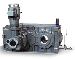
Image credit: Rexnord Corporation
An inching drive is used as an auxiliary system to the main drive for a large machine such as a ball mill, industrial kiln, conveyor, or elevator. Its purpose is to turn the equipment at a speed slower than the normal operating speed — typically 1 to 2 rpm, although fractional rpms are also common — and to do so at high torque — typically 120 percent of the normal drive torque.
Three main components make up the inching drive — an electric motor or internal combustion engine, a gear reducer, and a connecting element to automatically or manually engage with the equipment being driven. The use of either an electric motor or an internal combustion engine depends both on the type of equipment being driven and the conditions under which the inching drive will be used. For example, a kiln needs to be rotated constantly. If the main power supply fails, an inching drive with an internal combustion engine can rotate the kiln in the absence of power. But for most other types of equipment, the inching drive is used primarily during maintenance and repair operations. In these cases, electric motors are the more common choice because they can provide positioning accuracy and good holding capabilities.
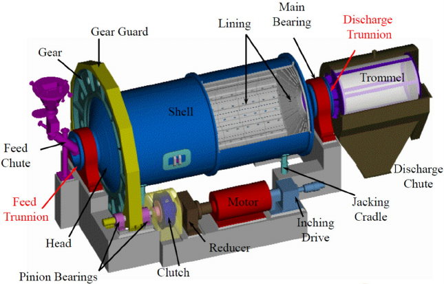
Image credit: Mauricio Neves, Arnaldo Andrade, and D.N. Silva
The mounting configuration of an inching drive can be parallel shaft, concentric shaft, or right angle. The mounting configuration is important for space considerations, but it also determines the type of gear reducer used in the inching drive. Parallel shaft configurations primarily use a helical gear or double-worm gear, although worm gears have low efficiency and are typically chosen only when self-locking is desirable. Concentric shaft designs also use helical gears, while right-angle designs most often use a combination of spiral bevel and helical gears.
In addition to the motor, gearbox, and coupling, most inching drive systems incorporate safety features, such as a brake or backstop, to prevent the drive from rotating when power is removed and to keep the equipment from rotating if it’s stopped in an unbalanced position.
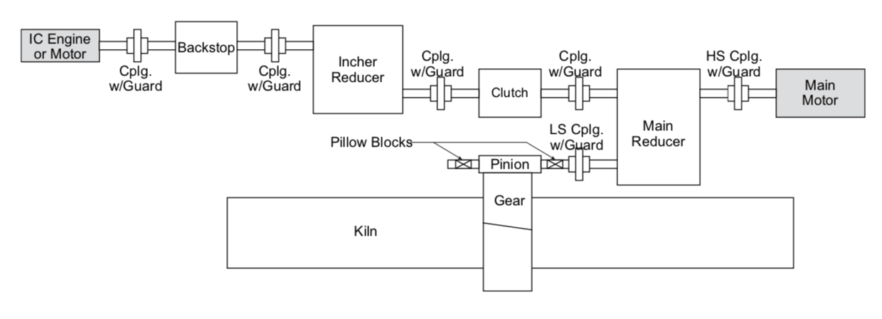
Image credit: IEEE Standards Association
A variable speed drive can generally provide inching or creeping capabilities — which eliminates the need for a separate inching drive — as long as the motor is capable of operating within the speed range required for inching.
Leave a Reply
You must be logged in to post a comment.